- Introduction
- The Diode: An Overview
- Prerequisites for Diode Testing
- Importance of Quality Testing Equipment
- Safety Precautions Before You Begin
- Testing Diodes with an Oscilloscope
- Diode Testing Using a Signal Analyzer
- Alternative Methods for Diode Testing
- Diode Testing Challenges and Solutions
- Delving Deeper: Advanced Diode Testing Techniques
- Conclusion: Mastering Diode Testing for Efficient Circuitry
- Whenever You’re Ready, Here Are 5 Ways We Can Help You
- Find Keysight's Precision Tools On Sale for Diode Testing
Ever found yourself puzzled over whether a diode in your circuit is performing as it should? You're in good company.
Diodes have a vital role, directing current and shaping signals in complex circuits. When they underperform, your entire system may suffer. That's why testing them isn't just good practice—it's essential.
Say goodbye to uncertainty. In this tutorial, we will dive into the indispensable tools for rigorous diode testing: oscilloscopes and signal analyzers.
These instruments are your ticket to precise measurements and reliable results. Get ready for a focused look into how to ensure your diodes are up to the task!
The Diode: An Overview
A diode serves as a semiconductor device that allows current to flow in one direction while blocking it in the opposite direction. With a simple two-terminal design, the diode's primary functions include rectification, signal clipping, and voltage regulation, among others. These devices come in various types—Zener, Schottky, Light Emitting (LED), and more—each with its unique characteristics and applications.
Ensuring a diode's optimal performance through rigorous testing is crucial. Sub-par diodes can cause signal distortion, energy loss, or even circuit failure.
Regular testing not only helps identify faulty diodes but can also extend the lifespan of the device. In high-stress applications like power electronics or automotive systems, more frequent testing becomes a necessity to preempt any malfunctions that could compromise the entire system.
Testing procedures for different types of diodes can vary.:
- Zener Diodes: Special attention goes to their breakdown voltage. A Zener diode works efficiently in reverse bias, so you'll often test for its ability to regulate voltage at its breakdown point.
- Schottky Diodes: These are known for low forward voltage drop and fast switching. Tests for Schottky diodes usually focus on their speed and efficiency, often using pulsed current tests.
- Light Emitting Diodes (LEDs): For LEDs, optical measurements like luminous intensity and wavelength come into play. Voltage-current characteristics also need checking to ensure efficient light emission.
Understanding the nuances between different types of diodes can guide you toward more accurate and useful testing, setting the stage for more robust and reliable circuits.
Prerequisites for Diode Testing
Before getting into the nuts and bolts of diode testing, the right foundation is indispensable. This includes investing in quality testing equipment and ensuring a safe testing environment.
Importance of Quality Testing Equipment
Quality should be your guiding principle when selecting testing equipment. Superior-grade instruments, such as those offered by Keysight, elevate your testing capabilities, allowing for accurate, in-depth analysis.
This means not just obtaining straightforward voltage and current measurements, but also capturing rapid transient responses and identifying minute irregularities that lesser equipment might overlook.
But quality doesn't end at purchase. The performance of even the best testing equipment can degrade over time due to wear and tear, environmental factors, or internal component drift.
This is where calibration steps in. Regular calibration checks and adjusts the accuracy of your instruments. It ensures that the readings you obtain today are as reliable as those you obtained yesterday, thereby maintaining the long-term integrity of your tests.
Don't underestimate the power of regular maintenance either. Cleaning your connectors, checking software for updates, and inspecting your cables can go a long way in preserving the reliability and lifespan of your equipment.
Safety Precautions Before You Begin
Even though diode testing is often considered routine, a lapse in safety measures can have consequences. Electrical shocks, fire hazards, or damage to the equipment or the diode under test—these risks make safety measures a priority.
Essential safety gear and workspace considerations:
- Safety glasses: A must-have for protecting your eyes against any sparks, or even small debris like a snapped wire.
- Insulated gloves: Don't underestimate the importance of gloves with proper electrical insulation. They serve as your first line of defense against electrical shocks.
- Non-conductive work surface: Using a rubber mat or a wooden table can prevent accidental grounding, thereby reducing the risk of electrical shocks or equipment damage.
- Isolated power supply: An isolated power supply can prevent ground loops, reduce electrical noise, and minimize the risk of dangerous shocks. It acts as an additional layer of safety for you and your equipment.
- Fire extinguisher: Having a Class C fire extinguisher at arm's length can be a real lifesaver, especially if you're working with high currents or voltages that could spark a fire.
By taking these safety precautions and equipment considerations seriously, you set the stage for accurate, reliable, and safe diode testing. This lays the groundwork for optimal circuit design and maintenance, setting you up for long-term success.
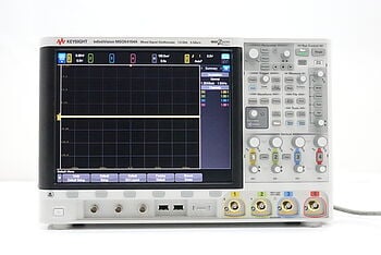
Testing Diodes with an Oscilloscope
An oscilloscope is an invaluable tool for any electrical engineer, offering a graphical representation of electrical signals. When it comes to diode testing, an oscilloscope gives you a real-time, visual representation of how the diode conducts and blocks current, effectively revealing its overall health and performance. Let's delve into the step-by-step procedure for testing a diode using this versatile instrument.
Step-by-Step Procedure:
- Setup: Turn on your oscilloscope and allow it a few minutes to warm up for stable readings.
- Probe connection: Connect your probe to the oscilloscope and use the probe's alligator or hook clip to attach it to the diode's anode and cathode.
- Settings: Set the oscilloscope to display a DC voltage scale that will cover the diode's expected forward and reverse bias voltages. For most diodes, a scale of -1V to +1V suffices.
- Signal injection: Apply a sinusoidal or square wave input to the diode. Ensure the amplitude and frequency are appropriate for your specific diode type.
- Interpretation of results: Analyze the waveform displayed on the oscilloscope. A healthy diode will show a clipped waveform, indicating proper function in both forward and reverse bias conditions.
Typical Oscilloscope Readings
| Condition | Functional Diode | Faulty Diode |
|---|---|---|
| Forward Bias | Clipped waveform above 0V | Unclipped or irregular waveform |
| Reverse Bias | Flatline or clipped at 0V | Spikes or irregularities |
Specialized Insights:
- Probe placement: Placement matters. Make sure to place the probe's tip accurately on the anode and the ground clip on the cathode for conventional diodes. For other types like Zener diodes, you may need to reverse this for certain tests.
- Waveform interpretation: A proper understanding of the displayed waveform can provide insights into the diode's condition. In forward bias, the waveform should be clipped above the diode’s forward voltage. In reverse bias, a flatline or a slight ripple indicates good health.
- Potential pitfalls: Be wary of factors like probe impedance, cable losses, or improper grounding. These can introduce errors in your readings. Also, a high-frequency input signal can sometimes make a faulty diode appear functional—so always cross-verify with DC tests.
By carefully following these steps and guidelines, you can use an oscilloscope to perform an effective, detailed analysis of diodes, making it easier to catch faults before they compromise your circuit's performance.
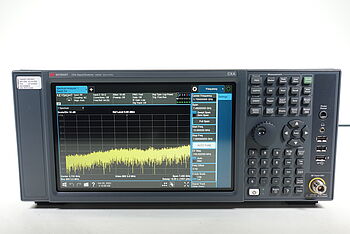
Diode Testing Using a Signal Analyzer
A signal analyzer measures and displays the magnitude and phase of the input signals in the frequency domain. In the context of diode testing, a signal analyzer can offer intricate details about the diode's frequency response, linearity, and even harmonic distortion, providing a more in-depth analysis than other testing methods.
Advantages and Unique Features
- Frequency domain analysis: Unlike time-domain instruments like oscilloscopes, signal analyzers operate in the frequency domain. This allows you to explore how the diode responds to different frequencies. You can identify resonance points, cut-off frequencies, and bandwidth limitations, giving you a complete picture of the diode's frequency response. This feature becomes particularly valuable when dealing with diodes in RF applications where frequency response is a critical parameter.
- Harmonic distortion measurement: Diodes can introduce harmonic distortion, especially when operated near their nonlinear regions. Signal analyzers can easily identify and quantify these harmonic components. By isolating and examining these harmonics, you can determine whether the diode is operating within specifications or if it's introducing unwanted distortions that could degrade overall circuit performance.
- High sensitivity: Signal analyzers are known for their high sensitivity and can detect even the slightest irregularities or deviations in the diode's performance. This enables you to spot early signs of wear and tear or impending failure that might be missed by other testing methods. High sensitivity is crucial when working on precision applications where even small diode inconsistencies can lead to significant issues.
- Automated measurements: Many modern signal analyzers come with built-in software functionalities that allow you to automate complex testing procedures. For example, you can program sequences to test a diode's response over a range of frequencies or amplitudes, and then automatically log the data. This not only speeds up the testing process but also ensures consistency in the measurements, especially useful for batch testing and quality control.
Step-by-Step Procedure
- Setup: Power up your signal analyzer and allow it some time to stabilize.
- Connection: Connect the diode between the signal generator output and the signal analyzer input. Ensure proper polarity orientation.
- Settings: Configure the signal analyzer to the desired frequency range and amplitude settings that are appropriate for your diode.
- Signal injection: Use the signal generator to apply a test signal to the diode.
- Understanding results: Examine the frequency spectrum and other parameters displayed to assess the diode's performance.
Typical Signal Analyzer Readings
| Parameter | Good Diode | Bad Diode |
|---|---|---|
| Frequency Response | Consistent across range | Irregularities observed |
| Harmonic Distortion | Low level or within spec | High or erratic levels |
| Linearity | Maintains curve shape | Deviates from curve |
Additional Insights:
- Frequency settings: Different types of diodes might require testing at various frequencies. For instance, Schottky diodes, known for fast switching, should be tested at higher frequencies.
- Amplitude considerations: The signal amplitude must be appropriate for the diode type. Too high of an amplitude can cause the diode to enter non-linear regions, while too low may not properly activate the diode.
- Detailed analysis: Signal analyzers often come with advanced features like phase measurement and marker functions, which can provide additional insights into the diode’s operation.
With a signal analyzer, you can delve deep into the complex behaviors of a diode, allowing you to evaluate its performance in different conditions and under various parameters. This makes it an invaluable tool for those looking to perform comprehensive diode testing.
Alternative Methods for Diode Testing
While oscilloscopes and signal analyzers offer thorough and detailed analysis, several alternative methods can also effectively test diodes. These options often suit scenarios where quick assessments or less complex analyses are necessary. Here's a rundown:
- Multimeter testing: A multimeter, set in diode testing or ohmmeter mode, can provide quick checks on diode functionality. In this mode, the multimeter applies a small voltage to the diode and measures the current, giving you an idea of its forward and reverse resistances.
- Curve tracer: A curve tracer plots the current-voltage (I-V) characteristics of a diode. This method gives you a more visual representation of how a diode performs over a range of voltages and is particularly useful for identifying non-linear behaviors.
- Functional circuit testing: Sometimes, the best way to test a diode is within the circuit it's meant to operate in. By using function generators and measuring circuit outputs, you can determine if the diode is doing its job, whether it's rectification, voltage regulation, or signal clipping.
- Component tester: Specialized component testers can identify various electronic components, including diodes, and perform basic tests to check their functionality. These are generally less precise than other methods but are convenient for quick identification and basic checks.
- Temperature testing: Diodes have a temperature coefficient that can be monitored to determine their health. By applying a voltage and observing how the diode's voltage drop changes with temperature, you can detect potential issues related to thermal stability.
- Computer-aided testing: Software tools that interface with hardware components can automate the testing process and analyze large sets of data quickly. These methods are particularly useful for batch testing or when developing new diode-based designs.
Each of these alternative methods has its advantages, limitations, and ideal use-cases. Consider the level of detail, available equipment, and specific characteristics to determine the ideal diode testing method. Evaluate, one of these methods might be just the right fit for your diode testing needs.
Diode Testing Challenges and Solutions
Testing diodes may appear straightforward, but several challenges can arise that might complicate the process. These issues can affect the accuracy of test results and, consequently, the performance of the circuits these diodes are a part of.
Let's explore some of these challenges and possible solutions.
Common Challenges
- Nonlinear behavior: Diodes don't behave like simple resistors; their voltage-current characteristics are nonlinear, which can make testing tricky.
- High-frequency limitations: In RF and microwave applications, the frequency response of the diode is critical, and not all testing methods can accurately measure high-frequency performance.
- Temperature sensitivity: Diodes are often sensitive to temperature changes, which can affect the reliability of test results.
- Microscopic defects: Physical inspections might not reveal internal defects or degradations, requiring more advanced methods for a thorough analysis.
- Automated testing complexities: When dealing with a large number of diodes, automated testing is ideal but often involves complicated setups and calibration efforts.
Solutions and Workarounds
- Use multiple testing methods: Combining the strengths of different methods, such as signal analyzers for frequency response and multimeters for quick checks, can offer a more complete picture.
- Temperature control: Use a temperature-controlled environment or compensating algorithms to normalize temperature variations during testing.
- Advanced equipment: For high-frequency and detailed analysis, using specialized equipment like signal analyzers can provide accurate results.
- Calibration: Regularly calibrate your testing equipment to ensure accurate measurements. This is crucial for both manual and automated setups.
- Expert consultation: When in doubt, consult experts or refer to diode datasheets for test parameter guidelines and acceptable performance ranges.
- Software aids: For automated testing, use software tools to set up complex tests, analyze data, and even provide pass/fail results automatically.
By being aware of these challenges and proactively employing these solutions, you can ensure that your diode testing is as accurate and reliable as possible. Whether you're dealing with a handful of diodes or running large-scale tests, these strategies can save you time and prevent costly errors.
Delving Deeper: Advanced Diode Testing Techniques
For professionals looking to go beyond basic diode tests, advanced techniques offer a deeper understanding of diode characteristics and behaviors. These methods can unearth subtle nuances, performance limitations, or even pending failures that standard tests might overlook.
Below are some of these advanced techniques, along with the additional tools you'll need.
1. Dynamic Resistance Measurement
- Description: Instead of measuring static forward or reverse resistance, this method focuses on how the resistance changes dynamically with applied voltage or current.
- Tools needed: Precision source-measure units (SMU), specialized software for real-time analysis.
2. Noise Figure Analysis
- Description: This test measures how much noise a diode adds to a system, a crucial metric in RF and high-frequency applications.
- Tools needed: Noise figure analyzer, noise sources, and specialized software for noise figure calculations.
3. Thermal Impedance Testing
- Description: Evaluates how efficiently a diode can dissipate heat, which impacts its longevity and performance in high-power applications.
- Tools needed: Thermal imaging camera, temperature-controlled environment, data acquisition system.
4. Spectral Content Analysis
- Description: Examines the spectral content of the diode’s output, identifying any unwanted frequency components or spurious emissions.
- Tools needed: Spectrum analyzer, near-field probes for in-situ testing.
5. Intermodulation Distortion (IMD) Analysis
- Description: IMD is the creation of new frequency components due to the interaction of two or more frequencies within a diode. Measuring IMD can indicate how a diode will behave in multi-tone environments.
- Tools needed: Two or more signal generators, spectrum analyzer, or specialized IMD measurement equipment.
6. Advanced Curve Tracing
- Description: Goes beyond simple I-V curve tracing by incorporating temperature, frequency, or other external variables.
- Tools needed: Advanced curve tracer with environmental chamber and frequency generator integration.
7. Pulsed I-V Measurements:
- Description: Measures a diode’s I-V characteristics under pulsed conditions, useful for understanding transient behavior.
- Tools needed: Pulse generators, oscilloscope with high sampling rate, or specialized pulse I-V equipment.
By employing these advanced techniques, professionals can delve into intricate details that can be vital for specialized applications, research, or high-reliability scenarios. Having a deeper understanding of your diodes ensures that your electronic circuits and systems operate at peak performance.
Explore Keysight's Precision Tools for Diode Testing


Conclusion: Mastering Diode Testing for Efficient Circuitry
Effective diode testing isn't just a procedural necessity; it's a cornerstone of reliable and efficient electronic circuitry. Diodes play pivotal roles in various circuit applications, from simple rectification tasks to complex signal modulation in high-frequency domains. Ensuring their optimal performance through rigorous and accurate testing is therefore imperative.
The tools you choose can make a significant difference in the depth and reliability of your testing. Oscilloscopes offer time-domain insights, capturing transient behaviors and allowing for visual waveform analysis.
On the other hand, signal analyzers excel in frequency-domain assessments, providing detailed harmonic distortion measurements, frequency response evaluations, and even automated functionalities for rapid and consistent analysis.
Precision in diode testing leads to impeccable circuit performance. While basic tests can provide quick insights, advanced techniques offer a level of understanding that can be invaluable for specialized or high-reliability applications.
Equip yourself with the best tools and techniques to make diode testing a straightforward yet comprehensive process. By doing so, you safeguard not just individual components but the entire electronic systems they serve, ensuring peak performance and long-term reliability.
Whenever You’re Ready, Here Are 5 Ways We Can Help You
- Browse our premium used network analyzers, oscilloscopes, signal analyzers and waveform generators.
- Call tech support US: +1 800 829-4444
Press #, then 2. Hours: 7am – 5pm MT, Mon– Fri - Talk to our sales support team by clicking the icon (bottom right corner) on every offer page
- Create an account to get price alerts and access to exclusive waitlists.
- Talk to your account manager about your specific needs.