- Introduction
- What is Impedance, and Why Does it Matter?
- How to Prepare for Measuring Impedance
- Choose the Correct Measurement Method
- Comparison Table
- Select the Right Instruments
- Set Up the Measurement Environment
- Precision Impedance Tools – Discover Keysight's Reliable Solutions
- Step-by-Step Guide to Measuring Impedance
- Step 1: Understanding the Circuit
- Step 2: Configuring the Instrument
- Step 3: Connecting the Circuit
- Step 4: Conducting the Measurement
- Step 5: Analyzing Measurement Results
- Factors Affecting Impedance Measurements
- Troubleshooting Common Issues
- Advanced Impedance Measurement Techniques
- Summary Table
- Real-World Applications of Impedance Measurement
- Need Speed & Quality? Browse Our Fast-Delivery Equipment
- Conclusion: Precision in Every Measurement
- Whenever You’re Ready, Here Are 5 Ways We Can Help You
How often have you faced challenges in your projects that boiled down to an issue with impedance? It's a vital concept that, when measured and understood correctly, can dramatically improve the performance and reliability of your systems.
Impedance isn't just a theoretical concept; it's a practical tool at the heart of your work. By measuring impedance accurately, you ensure that your circuits function efficiently, avoid unnecessary power losses, and prevent potential issues arising from impedance mismatches.
This guide is designed specifically for field engineers looking to sharpen their skills in impedance measurement. You'll find a clear, step-by-step approach that simplifies the process.
Whether designing a new system or troubleshooting an existing one, mastering impedance measurement is a skill that will set your work apart.
What is Impedance, and Why Does it Matter?
At its core, impedance (Z) is the total opposition a circuit presents to alternating current, encompassing both resistive (R) and reactive (X) components. It is expressed as Z = R + jX, where j represents the imaginary unit.
This complex number approach is crucial in AC circuits, offering a more nuanced understanding than simple resistance in DC circuits. For a complete guide on the impedance formula, click here.
Impedance is not just a theoretical concept but a practical tool that directly influences the performance and efficiency of electronic systems. Its measurement and control are vital in:
- Design: Ensuring compatibility and optimal performance of components.
- Troubleshooting: Identifying and rectifying issues in existing systems.
- Safety and efficiency: Minimizing power losses and preventing potential hazards.
In AC systems, impedance becomes a dynamic player, accounting for phase differences between current and voltage. This aspect is particularly critical in:
- Frequency-dependent behavior: Understanding how impedance varies with frequency is key in applications like filters and oscillators.
- Power systems: Ensuring stability and efficiency in power generation and distribution networks.
- Signal integrity: Critical in high-speed digital and RF communications for minimizing signal distortion and maximizing data integrity.
Mastering the measurement of impedance is not just about applying a formula. It's about integrating this knowledge into the fabric of your design and troubleshooting processes, ensuring that your projects meet and exceed expectations in performance and reliability.
How to Prepare for Measuring Impedance
Before diving into measuring impedance, it's crucial to lay the groundwork. Choosing the right measurement method is the first and perhaps most important step, as it can significantly impact the accuracy and reliability of your results.
Different methods suit different applications, and understanding their nuances is key to successful impedance measurement.
Choose the Correct Measurement Method
Various methods are available for measuring impedance, each with unique characteristics and applications. Let's explore some of the most commonly used techniques.
- Bridge method: This traditional method uses a bridge circuit to compare the unknown impedance with a known reference. Its advantage lies in its simplicity and effectiveness for low-frequency measurements. However, it may not be suitable for high frequencies or very low impedance values.
- I-V method: The current-voltage method involves applying a known voltage to a circuit and measuring the resulting current (or vice versa) to calculate impedance. This method is straightforward and versatile but can be less accurate if the phase relationship between voltage and current is not correctly accounted for.
- RF I-V method: Adapted for radio frequency measurements, this method extends the I-V method's principles to higher frequencies. It's ideal for RF applications but requires more sophisticated equipment to accurately measure phase differences at these frequencies.
- Automatically balanced bridge method: This modern method uses a feedback mechanism to automatically balance the bridge circuit. It offers high accuracy and is effective for a wide range of frequencies and impedances. However, it requires more complex instrumentation compared to traditional bridge methods.
Comparison Table
| Method | Frequency Range | Accuracy | Complexity | Best Use Cases |
|---|---|---|---|---|
| Bridge Method | Low | Moderate | Low | Basic, low-frequency applications |
| I-V Method | Broad | Good | Moderate | General purpose, versatile |
| RF I-V Method | High (RF) | Good to High | High | RF applications |
| Automatically Balanced Bridge | Broad | High | High | Precise, wide-range measurements |
Each method has its advantages and disadvantages, and the choice largely depends on the specific requirements of your project, such as the frequency range, desired accuracy, and available resources.
Select the Right Instruments
Selecting the right instruments is critical for accurate impedance measurements. Each piece of equipment has a specific role and suitability, depending on your measurement requirements. Let's go through some essential instruments for accurate impedance measurements.
- LCR meters: These are specialized for measuring inductance (L), capacitance (C), and resistance (R), which are integral components of impedance. LCR meters are highly versatile, offering precision in a variety of settings, from lab research to field service.
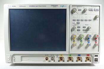
- Oscilloscopes: Essential for visualizing waveforms, oscilloscopes help in understanding the phase relationship between current and voltage, a crucial aspect in impedance measurements, especially in AC circuits.
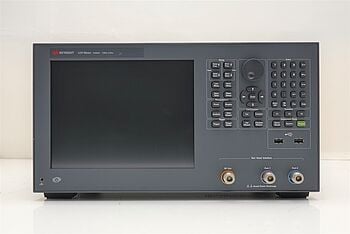
- Network Analyzers: These are advanced tools for measuring network parameters, including impedance. Network analyzers are ideal for high-frequency applications, providing detailed insights into the performance of complex RF components.
When choosing the instrument, consider factors like the frequency range, accuracy requirements, and specific parameters you need to measure. For instance, an LCR meter might be sufficient for basic impedance measurements, while a network analyzer would be necessary for detailed analysis in RF applications.
The quality of your equipment plays a significant role in the accuracy of your measurements. High-quality instruments ensure reliable and consistent results, which is crucial in engineering applications. Regular calibration of your equipment is also essential to maintain accuracy over time.
“Only Keysight offers a warranty on used equipment. Other resellers don’t.” - Keysight Account Manager
Set Up the Measurement Environment
Preparing the right environment is crucial for obtaining accurate impedance measurements. Environmental factors like temperature, humidity, and electromagnetic interference can significantly affect the results. Here's how to control these factors.
- Temperature: Ensure your measurement environment has a stable temperature, ideally within a controlled laboratory setting. If you're working in the field, try to minimize exposure to sudden temperature changes.
- Humidity: High humidity levels can lead to condensation and affect the electrical properties of components. Maintain a low-humidity environment to prevent such issues. Use dehumidifiers in the lab to help control humidity levels.
- Electromagnetic Interference (EMI):EMI can distort impedance measurements, especially in sensitive or high-frequency applications. Conduct measurements in a shielded environment whenever possible to minimize the effects of external electromagnetic fields. Using Faraday cages or shielded rooms can be effective in reducing EMI.
By carefully controlling these environmental factors, you can ensure that your impedance measurements are accurate and reliable.
Precision Impedance Tools – Discover Keysight's Reliable Solutions


Step-by-Step Guide to Measuring Impedance
You’ve prepared your measurement environment and selected the right tools, now it's time to measure impedance! This step-by-step guide will walk you through the critical stages, from understanding the circuit in question to configuring your measurement instruments.
Step 1: Understanding the Circuit
The first step is to thoroughly analyze the circuit or component whose impedance you need to measure.
- Identify components and connections: Knowing the layout and components of the circuit helps in determining where and how to measure impedance.
- Expected impedance range: Estimating the expected impedance range will help you to choose the right measurement settings and instruments. For instance, a circuit designed to operate at high frequencies might require a different approach compared to a low-frequency power circuit.
Step 2: Configuring the Instrument
Once you have a clear understanding of the circuit, proceed to set up your chosen impedance measurement instrument. Here’s what you need to do:
- Instrument setup: Based on the impedance range and characteristics of the circuit, configure the instrument settings appropriately. This might include setting the frequency range, measurement parameters, and specific modes or functions relevant to your circuit.
- Calibration: Before starting measurements, ensure that your instrument is calibrated. Calibration is vital for accuracy, especially in precision applications. Follow the manufacturer’s instructions for calibration, and use standard calibration kits if available.
“For all used equipment, we offer clients calibration and 1-year warranty.” – Keysight Account Manager
Step 3: Connecting the Circuit
To safely connect the circuit or component to your measurement instrument, follow these guidelines:
- Power off: Ensure that the circuit is powered off before making any connections. This step is crucial for safety and to prevent damage to the circuit or the instrument.
- Correct connections: Refer to the circuit diagram and the instrument manual to make the correct connections. Typically, this involves connecting the test leads to the points where impedance needs to be measured.
- Secure connections: Check that all connections are secure and free from loose wires or bad contacts, as these can lead to inaccurate measurements.
The importance of ensuring secure and correct connections cannot be overstated. Improper connections can lead to erroneous readings and potentially damage the instrument or the circuit.
Step 4: Conducting the Measurement
Once the circuit is safely connected, you can initiate the impedance measurement process:
- Start measurement: Power on the instrument and start the measurement process as per the instructions specific to your equipment.
- Stable readings: Wait for the readings to stabilize. Impedance measurements can fluctuate initially, especially in reactive circuits.
- Record measurements: Accurately record the measurements. It's advisable to take multiple readings to ensure consistency.
Step 5: Analyzing Measurement Results
Interpreting the impedance measurement results is the final step in the process. Here are some common patterns and their potential implications:
- Higher than expected impedance: This result could indicate an open circuit, poor connections, or degraded components.
- Lower than expected impedance: This result might suggest a short circuit or components that are bypassing part of the circuit.
- Frequency-dependent changes: If impedance varies significantly with frequency, this could be characteristic of reactive components like inductors and capacitors.
- Consistent with expected values: If the measured impedance aligns with expectations, it suggests that the circuit is functioning as intended.
Understanding these patterns helps you make informed decisions about the circuit’s performance and necessary adjustments or repairs.
Factors Affecting Impedance Measurements
Several factors can influence the accuracy of impedance measurements. Being aware of these can help you ensure more reliable and precise results. Here are some key factors to consider:
Parasitic Elements
- Capacitance and inductance: Parasitic capacitance and inductance from the components, circuit board, or even the measuring instrument can affect readings.
- Resistive losses: Parasitic resistance can also introduce errors, especially in high-frequency measurements.
Cable Characteristics
- Length: Longer cables can introduce additional inductance and capacitance, affecting the measured impedance.
- Type and quality: The type and quality of the cables used for connections play a significant role. Low-quality cables can introduce noise and resistance that skew results.
- Shielding: Properly shielded cables are essential, particularly in environments with high electromagnetic interference.
Physical Properties of Components
- Temperature coefficient: Many components have impedance values that vary with temperature, so ambient and component temperatures can impact readings.
- Age and wear: Over time, components can degrade, changing their electrical characteristics. This factor is particularly crucial in maintenance and troubleshooting scenarios.
- Material properties: The intrinsic properties of the materials used in the components, like dielectric constants and conductive properties, can also affect impedance measurements.
Measurement Frequency
- Frequency range: Accurate impedance measurements are crucial for effective design, testing, and troubleshooting of electrical and electronic systems. Understanding and controlling these factors is essential.
- Harmonics: Unwanted harmonics in the test signal can distort impedance measurements, leading to inaccurate readings.
Test Setup and Methodology
- Connection integrity: Loose or poor connections can introduce errors.
- Method selection: The measurement method (e.g., bridge method, LCR meter) can impact the accuracy, depending on the application.
Understanding and controlling these factors are vital for achieving accurate impedance measurements, essential for the effective design, testing, and troubleshooting of electrical and electronic systems.
Troubleshooting Common Issues
Here are solutions for typical problems you might encounter during impedance measurements:
Inconsistent Readings
- Check connections: Ensure all connections are secure and free from corrosion or damage.
- Stabilize environment: Variations in temperature or humidity can affect readings. Try to maintain a stable measurement environment.
- Review instrument settings: Incorrect settings on your measurement instrument can lead to inconsistent results. Double-check these settings.
Unexpectedly High or Low Values
- Inspect for circuit issues: Look for signs of open circuits (high impedance) or short circuits (low impedance).
- Evaluate component health: Degraded or faulty components can give unexpected readings. Test individual components if possible.
- Consider parasitic elements: Parasitic capacitance, inductance, and resistance can skew readings. Evaluate your circuit layout for potential sources.
Noise in Measurements
- Use shielded cables: To minimize electromagnetic interference, opt for shielded cables.
- Filter test signal: Apply filtering to reduce noise in the test signal.
- Check grounding: Proper grounding of the circuit and instrument can reduce noise.
Device Overheating
- Check power levels: Ensure that the power levels in the circuit are within the safe operating limits of the components.
- Improve ventilation: Increased airflow around the device can help dissipate heat.
Difficulty in Measuring at High Frequencies
- Use suitable instruments: Ensure your measurement tools are designed for high-frequency operation.
- Minimize lead lengths: Longer leads can add unwanted inductance and capacitance at high frequencies. Keep leads as short as practical.
Addressing these common issues can greatly improve the accuracy and reliability of your impedance measurements, leading to better performance and durability of your electrical and electronic systems.
Advanced Impedance Measurement Techniques
For specialized applications, particularly in high-frequency domains, precision engineering, and materials science, advanced impedance measurement techniques are required. Here are some of these techniques.
Time Domain Reflectometry (TDR)
- Application: Used for characterizing and locating faults in cables, PCB traces, and connectors.
- Benefits: Offers high resolution and can pinpoint the exact location of impedance discontinuities.
Impedance Spectroscopy
- Application: Ideal for analyzing the frequency-dependent characteristics of materials and electrochemical systems.
- Benefits: Provides comprehensive data over a wide frequency range, crucial for understanding complex impedance behavior.
On-Wafer Measurements
- Application: Essential in semiconductor manufacturing for evaluating the impedance of microscale devices directly on the wafer.
- Benefits: Allows for the testing of devices without the need for individual packaging, saving time and resources.
Vector Network Analysis
- Application: Used in RF and microwave engineering for measuring the complex impedance of high-frequency components and systems.
- Benefits: Offers highly accurate measurements of amplitude and phase, crucial for high-frequency applications.
Summary Table
| Technique | Applications | Benefits |
|---|---|---|
| TDR | Cable/PCB fault locating | High resolution, precise fault location |
| Impedance Spectroscopy | Material analysis, electrochemistry | Wide frequency range, detailed impedance profile |
| On-Wafer Measurements | Semiconductor manufacturing | Direct wafer-level testing, resource-efficient |
| Vector Network Analysis | RF and microwave engineering | High accuracy in amplitude and phase |
Real-World Applications of Impedance Measurement
Impedance measurement plays a crucial role in various fields of engineering. Here are some key applications.
- Electronics design and testing: Tune circuit parameters for optimal performance in audio and video equipment. In consumer electronics, impedance measurement is crucial for designing efficient and compact power supplies.
- Telecommunications: Ensures impedance matching in antennas and transmission lines for clear signal transmission. Impedance measurements are vital in optimizing the performance of cellular network components.
- Power systems: Monitors transformer and generator impedances to prevent power losses and ensure efficient energy distribution. Used in the design of renewable energy systems, like solar inverters, to enhance power quality and conversion efficiency.
- Biomedical engineering: Measures bioimpedance for body composition analysis and monitoring physiological conditions. Development of impedance-based sensors for non-invasive monitoring of blood flow and respiratory functions.
- Material science: Characterizes the electrical properties of conductive and semiconductive materials. Assesses the quality and consistency of nanomaterials used in advanced manufacturing processes.
- Automotive industry: Tests impedance in battery systems and electrical components of vehicles for safety and efficiency. Ensures the reliability of electronic control systems in modern vehicles, including electric and hybrid models.
- Aerospace engineering: Impedance measurements in avionics for reliable communication and navigation systems. In spacecraft design, impedance measurement assists in the development of robust communication links and onboard electronic systems.
Need Speed & Quality? Browse Our Fast-Delivery Equipment
Conclusion: Precision in Every Measurement
The importance of impedance measurement in engineering is clear. Every step plays a vital role in ensuring accurate and reliable measurements.
The relevance of impedance measurement spans a wide range of applications, from designing sophisticated electronics to innovations in biomedical engineering. The advanced techniques and practical examples we've discussed show how crucial it is in various engineering fields.
Remember, choosing the right tools for impedance measurement goes beyond just looking at specifications. It's about ensuring that every project you undertake is marked by precision and reliability.
With Keysight, you're not just conducting measurements; you're upholding a standard of excellence in your engineering projects. Precision in every measurement is not just an objective; it's a promise of quality and dependability.
Whenever You’re Ready, Here Are 5 Ways We Can Help You
- Browse our premium used network analyzers, oscilloscopes, signal analyzers and waveform generators
- Call tech support US: 1 800 829-4444. Press #, then 2. Hours: 7 am – 5 pm MT, Mon– Fri
- Talk to our sales support team by clicking the icon (bottom right corner) on every offer page
- Create an account to get price alerts and access to exclusive waitlists
- Talk to your account manager about your specific needs.