- Introduction
- A Brief History of Oscilloscopes: How They Evolved
- Essential Parts of an Oscilloscope: An In-Depth Overview
- Cathode-Ray Tube (CRT)
- Display System
- Vertical System
- Horizontal System
- Trigger Systems
- Probes and Input Channels
- Control Panels
- Troubleshooting Common Problems
- Summary Table
- Advanced Features in Modern Oscilloscopes
- Choosing the Right Oscilloscope for Your Needs: A Keysight Perspective
- Understand Your Requirements
- Consider the Application
- Conclusion: Empowering Your Work with Knowledge
- Final Key Takeaway: Innovation Through Understanding
- Whenever You’re Ready, Here Are 5 Ways We Can Help You
Scientists have powerful telescopes at their disposal to decode the secrets of the universe. Now, replace that telescope with an oscilloscope, and the universe with the world of electronic signals. Every day, electrical engineers deal with complex waves and frequencies that are fundamental to our connected world.
The oscilloscope, an indispensable piece of equipment in signal analysis, helping engineers uncover the hidden rhythms of electricity. Yet, this essential tool comes with its own intricacies and complexities that require a skilled hand to navigate.
By delving into the parts and functions of the oscilloscope, we can unlock its true potential. These vital tools are the key to new insights in engineering, providing precision and unparalleled insight. So come along as we explore this intricate device in detail, guided by the experience and wisdom of industry leaders like Keysight.
A Brief History of Oscilloscopes: How They Evolved
Oscilloscopes have undergone a fascinating evolution, transforming from rudimentary devices into advanced tools central to modern engineering. Here's a snapshot of their journey:
- Early beginnings (1900s): The first oscilloscope, called an "oscillograph," used a moving pen to record changes in electrical voltage on a rotating drum. It was a basic yet groundbreaking invention.
- Cathode ray era (1930s): The invention of the cathode-ray oscilloscope marked a significant advancement: displaying waveforms on a screen. This technology laid the groundwork for modern oscilloscopes.
- Digital revolution (1980s): Transitioning from analog to digital, oscilloscopes began employing microprocessors. This shift allowed for more features, such as digital storage and complex data analysis.
- Modern age (2000s – Present): Today, digital scopes offer incredible precision, connectivity, and versatility. They can analyze a vast array of signals and are essential tools in various fields like telecommunications, medicine, and automotive engineering.
Keysight has played a crucial role in developing modern oscilloscope technology. They have introduced innovations such as InfiniiVision and Infiniium, which have set industry standards and pushed the limits of what was previously possible. The role of industry leaders like Keysight has been instrumental in this progress, bringing us the sophisticated oscilloscopes that engineers rely on today.
Essential Parts of an Oscilloscope: An In-Depth Overview
The oscilloscope comprises various intricate components that work together to analyze and visualize complex electronic signals. Here's a list of the main parts:
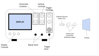
- CRT (Cathode Ray Tube): Acting as the heart of traditional analog oscilloscopes, the CRT generates electron beams to create visual displays of waveforms.
- Display: Whether a phosphor screen in analog scopes or a digital LCD in modern ones, the display translates complex data into visual waveforms that engineers can interpret.
- Vertical system: This part controls the amplitude of the signal, allowing adjustments to how the waveform stretches or compresses vertically on the display.
- Horizontal system: Governs the time base and allows engineers to control the horizontal scaling of waveforms, essential for examining frequency and time relationships.
- Trigger systems: Ensures stability and clarity of the waveform; the trigger systems detect specific events in the signal, providing a stable and repeatable display.
- Probes and input channels: Acts as the link between the circuit under test and the oscilloscope. These components provide various connection options and enable accurate measurements.
- Control panels: The command center of the oscilloscope, control panels offer knobs, buttons, and interfaces for precise control and customization of measurements.
Understanding these parts equips an engineer with the ability to operate an oscilloscope with confidence and mastery. Each component contributes to the device's multifaceted capabilities, creating a tool that's as versatile as it is essential.
In the following sections, we'll delve deeper into each of these components, unlocking the secrets of what makes the oscilloscope an invaluable instrument in the modern engineering world.
Cathode-Ray Tube (CRT)
A CRT is a vacuum tube containing one or more electron guns, along with a phosphorescent screen. The electron guns emit beams, which are deflected across the screen by electric or magnetic fields. When the electron beams strike the phosphorescent screen, they cause it to glow, thus creating a visible pattern.
In the context of an oscilloscope, the CRT's function is to translate the electronic signals from a circuit into a visual waveform. As the beams sweep across the screen in a controlled manner, they draw the shape of the waveforms, allowing engineers to see variations in voltage or current over time.
The introduction of the CRT marked a revolutionary advancement in oscilloscope technology. Before digital displays, CRTs offered the only way to visually represent electronic signals. Their invention allowed for the first real-time, continuous observation of waveforms, providing engineers with unprecedented insights into the behavior of electrical circuits.
Though replaced by digital displays in modern oscilloscopes, the CRT remains an iconic symbol of a transformative period in technology. It bridged the gap between the abstract world of electrical signals and the tangible realm of visual interpretation, laying the groundwork for the sophisticated oscilloscopes we use today. Understanding the CRT is not merely a study of an outdated component but a tribute to a pivotal innovation that shaped the field of electronic engineering.
Display System
The display system in modern oscilloscopes has evolved far beyond the traditional CRT, embracing digital technologies like LCDs and other advanced screens. This evolution has led to more flexible, precise, and visually appealing ways to represent complex electronic signals.
Types of Displays
- LCD (Liquid Crystal Display): Widely used in modern oscilloscopes, LCDs offer sharp images, low power consumption, and lightweight design. They employ liquid crystals to manipulate light, providing a crisp visual representation.
- OLED (Organic Light-Emitting Diode): Some high-end oscilloscopes use OLED displays, known for their bright and vibrant colors, high contrast ratios, and wide viewing angles.
- TFT (Thin-Film Transistor): This technology offers better image quality and response time, allowing for more precise visualization of rapid signal changes.
Resolutions
The resolution of the display determines the clarity and detail of the waveform. Higher resolution screens allow for more precise observation and analysis, essential for intricate tasks. Typical resolutions range from 800x600 to 1920x1080 pixels, depending on the oscilloscope's model and purpose.
Grid Layouts
Modern displays often feature customizable grid layouts, divided into divisions or "boxes." These grids assist engineers in measuring and comparing signals by providing a reference framework. The most common grid layout consists of 8x10 divisions, but many oscilloscopes allow users to tailor this to their specific needs.
Visual Representations of Data
Today's oscilloscope displays can represent data in various ways, including:
- Waveform views: Traditional line-based representations of voltage or current over time.
- 3D and color views: Utilizing color and three-dimensional rendering to represent additional data dimensions, such as intensity or multiple channel overlays.
- On-screen measurements: Modern screens often display key measurements and statistics directly on the screen, offering real-time insights without the need for manual calculations.
The transition from CRT to modern digital displays represents a leap in both technology and usability. These advanced screens not only provide a clearer and more versatile view of electronic signals but also enrich the user's interaction with the data. The combination of different display types, resolutions, grid layouts, and visual representation techniques puts a powerful tool in the hands of today's engineers, allowing them to explore and understand the electronic world with unparalleled depth and precision.
Vertical System
The vertical system in an oscilloscope serves as a critical control mechanism for the display and analysis of waveforms. It allows for the manipulation of the vertical aspects of the signal, including scaling, positioning, and channel selection, and also impacts bandwidth considerations. Here's an in-depth look at these essential functions.
Vertical Controls
The vertical controls enable the adjustment of the amplitude representation on the screen. By altering these controls, an engineer can zoom in or out on the waveform, focusing on details or obtaining an overview.
Scaling
Scaling refers to the adjustment of the vertical size of the waveform on the display. By changing the volts-per-division (V/div) setting, one can stretch or compress the waveform vertically. This function allows for detailed examination of specific amplitude characteristics or a broader view of the entire waveform.
Positioning
The vertical positioning control allows for the movement of the waveform up or down on the screen. This ability is particularly useful when comparing multiple waveforms or when focusing on a specific part of the signal without changing the scaling.
Channel Selection
Modern oscilloscopes often come with multiple channels, enabling the simultaneous observation of several signals. The vertical system allows for the selection and individual adjustment of these channels. Engineers can use this function to compare signals, identify relationships, or isolate specific behaviors.
Bandwidth Considerations
Bandwidth in the vertical system refers to the range of frequencies the oscilloscope can accurately display. An oscilloscope's bandwidth must be higher than the frequency of the signal under examination to ensure accurate representation. Bandwidth considerations impact the ability to analyze high-frequency components and transient behaviors within the signal.
The vertical system provides an essential interface for the customization and control of how waveforms are viewed on the oscilloscope. Understanding and skillfully using the vertical system elevates the power of the oscilloscope from a mere visualization tool to a precise analytical instrument, unlocking deeper insights into the behavior and nature of electrical phenomena.
Horizontal System
The horizontal system in an oscilloscope is equally vital as the vertical system, focusing on the control and representation of time-related aspects of a signal. From scaling to delay settings, it offers tools to dissect and explore the time domain of waveforms. Here's a breakdown of these critical functions.
Horizontal Controls
Horizontal controls manipulate the horizontal aspects of the waveform, primarily affecting how the time element of the signal is displayed and analyzed.
Scaling
The horizontal scaling, also referred to as the time-per-division (s/div or ms/div) setting, determines how much time is represented by each horizontal division on the screen. By adjusting this setting, engineers can either compress the waveform to see a longer time span or stretch it to focus on minute details within a shorter time frame.
Time Base
The time base controls the rate at which the waveform is drawn across the screen. It serves as the "ruler" for time measurement and can often be set to different modes, such as continuous sweep or single-shot, depending on the type of signal analysis required.
Delay Settings
Delay functions allow engineers to shift the visible portion of the waveform to the left or right on the display. This capability is particularly valuable when investigating specific segments of a signal or when synchronizing multiple waveforms for comparative analysis.
Other Time-Related Functions
Modern oscilloscopes may include additional time-related functions such as:
- Zooming: This feature allows engineers to select a specific portion of the waveform and magnify it for detailed inspection.
- Time markers: Some oscilloscopes offer time markers that facilitate precise measurement of time intervals between specific points on the waveform.
- Record length: This determines how many data points the oscilloscope can capture within a given time window, impacting the resolution and detail of the recorded waveform.
The functionality of the horizontal system highlights the vital importance of time in signal analysis. By granting detailed control over how time is represented and manipulated, it adds a rich layer of interpretative power to the oscilloscope.
Whether compressing a long signal into a comprehensible view or diving into the microscopic world of nanoseconds, the horizontal system provides the keys to a comprehensive understanding of the temporal aspects of electrical phenomena.
Trigger Systems
Trigger systems in an oscilloscope play a fundamental role in stabilizing the viewing of waveforms and capturing specific events within a signal. By selecting particular conditions that must be met for a waveform to be displayed, the trigger system ensures that the relevant parts of the signal are visible and clearly defined. Here's an exploration of the various triggering methods, types, settings, and their functions.
Triggering Methods
- Edge triggering: The most common form, edge triggering, captures a waveform when the signal crosses a specified voltage level in a defined direction (rising or falling edge).
- Pulse triggering: This method triggers on specific pulse characteristics like width, duration, or missing pulses, useful for capturing anomalies.
- Video triggering: Designed for analyzing video signals, this method synchronizes with specific lines or fields in standard video formats.
Types of Triggers
- Auto trigger: If no trigger condition is met within a specific time, an automatic trigger displays the waveform anyway, ensuring a constant display.
- Normal trigger: The waveform is displayed only when the trigger conditions are met, providing a stable view of a specific event.
- Single trigger: This captures a single event, freezing the display to allow detailed analysis of a specific waveform occurrence.
Settings
Trigger level: This sets the voltage level at which the trigger activates, allowing for precise control over what part of the signal is captured.
Trigger slope: This setting helps determine if the trigger activates when the signal rises or falls, allowing focus on specific transitions.
Holdoff time: This setting helps prevent multiple triggers on complex waveforms by disabling triggering for a period of time after each trigger event.
Stabilizing Waveform Viewing
The trigger system's primary role is to stabilize the waveform on the display, ensuring that the same portion of the signal is shown repeatedly. Without effective triggering, the waveform would drift horizontally, making analysis challenging. By locking onto specific characteristics of the signal, triggering allows for a clear and stable display, enabling precise measurements and insightful observations.
Trigger systems are instrumental in converting a chaotic and continuously varying signal into a stable and analyzable visual representation. By offering a range of methods, types, and finely tunable settings, they provide engineers with powerful tools to explore, dissect, and understand intricate waveforms.
Mastering triggering techniques transforms the oscilloscope from a simple monitoring device into a sophisticated analytical instrument, capable of revealing the hidden subtleties and behaviors within electronic signals.
Probes and Input Channels
Probes and input channels are integral to an oscilloscope's functionality, serving as the critical interface between the circuit under test and the oscilloscope itself. They facilitate the accurate transmission and representation of signals, requiring careful consideration of various factors. Below, we explore different types of probes, impedance considerations, channels, coupling options, and attenuation.
Types of Probes
- Passive probes: Simple, low-cost, and most common, these probes have high impedance and are suitable for general-purpose measurements.
- Active probes: Featuring built-in amplifiers, active probes provide higher bandwidth and lower loading effects but are usually more expensive.
- Current probes: Specifically designed to measure current, current probes often employ a Hall sensor or a current transformer.
- Differential probes: These probes measure the voltage difference between two points, minimizing noise and providing isolation from the common ground.
Impedance Considerations
Matching the impedance of the probe with the oscilloscope input and the circuit minimizes signal distortion. Typical oscilloscope inputs have 1 MΩ impedance, but 50 Ω options are also available for specific applications.
Channels
Modern oscilloscopes often include multiple input channels, allowing simultaneous observation of several signals. Multiple channels enhance the oscilloscope's capability to analyze complex circuits, relationships between signals, and perform comparative studies.
Coupling Options
AC coupling: Blocks DC components and allows only AC signals to pass, useful for observing small AC signals superimposed on large DC levels.
DC coupling: Permits both AC and DC signals, providing a complete view of the signal.
Ground coupling: Connects the input directly to the ground, used for zeroing the trace before making measurements.
Attenuation
Probes may come with selectable attenuation ratios, such as 1:1 or 10:1. Higher attenuation reduces loading effects but also decreases signal amplitude. Accurate compensation and calibration are necessary to maintain measurement accuracy.
Probes and input channels are the gateways through which an oscilloscope sees the electronic world. Selecting the right probe, understanding impedance matching, utilizing multiple channels, choosing appropriate coupling, and handling attenuation are essential skills that elevate the effectiveness of an oscilloscope.
Control Panels
The control panel of an oscilloscope serves as the command center, allowing the user to manipulate settings, navigate menus, and interact with the device. A well-designed control panel enhances the usability of the oscilloscope, providing intuitive access to complex functionalities. Here's a closer look at the various elements that make up the control panel:
Function Keys
Function keys are dedicated buttons designed to provide quick access to specific features or commands. They may include:
- Vertical and horizontal controls: These allow adjustments to the scaling, positioning, and other attributes of the waveforms.
- Trigger controls: Quick settings for triggering methods, types, and thresholds.
- Measurement keys: Dedicated buttons to initiate common measurements like frequency, amplitude, or phase.
- Utility or special function keys: These may offer access to more advanced features, custom settings, or user-defined functions.
Menu Systems
Modern oscilloscopes often come with digital menu systems that allow navigation through various options and settings. These can include:
- On-screen menus: Interactive display menus guide the user to select modes, channels, or configurations.
- Sub-menus: Layered organization allows for more detailed adjustments without cluttering the main interface.
- Context-sensitive menus: These appear based on the current mode or selection, ensuring that relevant options are always readily available.
User Interface Design
User interface (UI) design significantly influences the overall experience of using an oscilloscope. Key considerations include:
- Layout: The arrangement of buttons, knobs, and displays should facilitate a natural workflow, with frequently used controls easily accessible.
- Labels and icons: Clear, descriptive labeling and intuitive icons help users quickly identify functions.
- Ergonomics: The design should consider the physical comfort of the user, with controls placed within convenient reach.
- Touchscreen Interaction: Many modern oscilloscopes feature touchscreen interfaces, blending the traditional controls with a more versatile digital interaction.
Control panels in an oscilloscope embody the bridge between human intention and electronic inquiry. They translate user commands into precise adjustments, measurements, and analyses. A well-structured control panel not only simplifies complex tasks but elevates the overall efficiency and satisfaction in using the oscilloscope. As technology continues to evolve, the fusion of tactile controls with intelligent digital interfaces is reshaping the interaction between engineers and their tools.
Troubleshooting Common Problems
It is common to come across issues or malfunctions in specific components when working with oscilloscopes. It is vital that you understand how to diagnose and fix these issues. Here's a guide to common problems and their solutions, summarized later in a table.
Display System
A fuzzy or distorted display can be frustrating. This issue may be due to a resolution mismatch, calibration error, or a hardware problem. Adjusting the display settings to the expected resolution, recalibrating, or consulting the manual for hardware troubleshooting steps can often fix the issue.
Vertical and Horizontal Systems
Unstable or drifting waveforms may be related to improper scaling, triggering settings, or hardware malfunctions. Correcting the scaling, verifying the triggering settings, or following the manufacturer's guidelines for hardware diagnostics can stabilize the waveforms.
Trigger Systems
Inconsistent or failed triggering might be the result of improperly set trigger levels or types, or a hardware issue. Verifying and adjusting the trigger settings, consulting the manual for specific guidance, or seeking professional service if a hardware problem is suspected can resolve this problem.
Probes and Input Channels
Inaccurate readings or signal distortion can occur due to improper probe compensation, impedance mismatch, or faulty probes. Recalibrating the probe, ensuring proper impedance matching, or replacing defective probes can lead to accurate readings.
Control Panels
Unresponsive or erratic controls might be due to a software glitch or a hardware fault. Restarting the oscilloscope or performing a factory reset if needed can restore normal operation.
Summary Table
| Component | Common Problem | Diagnosis Strategy | Suggested Solution |
|---|---|---|---|
| Display System | Fuzzy or distorted display | Check resolution, calibration | Adjust settings, recalibrate |
| Vertical/Horizontal Systems | Unstable waveforms | Verify scaling, triggering settings | Adjust settings, consult manual |
| Trigger Systems | Inconsistent triggering | Check trigger settings | Adjust settings, seek service if needed |
| Probes/Input Channels | Inaccurate readings | Check probe compensation, impedance | Recalibrate, replace probes |
| Control Panels | Unresponsive controls | Restart, check for glitches | Restart, factory reset, seek service |
By understanding these common problems and having a structured approach to diagnose and fix them, you enhance the reliability and efficiency of using an oscilloscope. Always consult the specific user manual or manufacturer's support for detailed guidance tailored to your particular oscilloscope model, as they may vary in design and functionality.
Advanced Features in Modern Oscilloscopes
Modern oscilloscopes are not just tools for viewing waveforms; they have evolved into sophisticated instruments capable of in-depth analysis and complex operations. Engineers and researchers are increasingly relying on these advanced features, as they offer unprecedented insights and capabilities. Here, we'll explore some of the unique characteristics and functions found in contemporary oscilloscopes.
Mixed Signal Capability
Mixed signal oscilloscopes (MSOs) combine the features of a traditional oscilloscope with those of a logic analyzer. This combination allows simultaneous analysis of both analog and digital signals, providing a comprehensive view of the system's operation. MSOs have become indispensable in designing and debugging digital systems, where precise timing correlations between analog and digital components are crucial.
Waveform Mathematics
Waveform mathematics allows users to perform mathematical operations on waveforms directly within the oscilloscope. Functions such as addition, subtraction, multiplication, division, integration, and differentiation enable real-time signal processing and analysis. This feature can significantly enhance the understanding of complex systems, as well as facilitate the development of control algorithms or filter designs.
Signal Integrity Tools
Modern oscilloscopes often come with specialized signal integrity tools that allow the visualization and measurement of jitter, noise, crosstalk, and other parameters affecting signal quality. These tools are vital in high-speed digital design, where small imperfections can have a significant impact. Assessing signal integrity helps in optimizing layouts, selecting proper components, and ensuring reliable system performance.
Protocol Analysis
With the proliferation of various communication protocols in electronic systems, oscilloscopes now offer protocol-specific triggering and decoding capabilities. Whether working with I2C, SPI, USB, or other protocols, these features enable precise analysis and debugging of communication between devices. This functionality is particularly valuable in embedded system development, where smooth communication is essential.
Spectrum Analysis
Some oscilloscopes incorporate spectrum analysis functions, allowing users to view signals in the frequency domain. This dual time-frequency view enables detailed analysis of signal characteristics, identification of undesired spectral components, and measurement of harmonic content. Such features are particularly valuable in RF design and EMC compliance testing.
Automated Measurement and Reporting
The ability to automate measurements and generate detailed reports directly from the oscilloscope saves considerable time and effort. Automated functions may include statistical analysis, trend plotting, limit testing, and customizable report generation. These features streamline the documentation process and ensure consistency and accuracy in repeated measurements.
The modern oscilloscope is a versatile and powerful instrument, equipped with an array of advanced features that transcend traditional signal visualization. Whether analyzing mixed signals, performing complex waveform mathematics, ensuring signal integrity, or exploring new customization possibilities, today's oscilloscopes are vital partners in the journey of technological exploration and innovation.
Choosing the Right Oscilloscope for Your Needs: A Keysight Perspective
Selecting the right oscilloscope is a critical decision that can significantly impact the success of your projects. With various models and an array of features available, the choice may seem overwhelming. As a leader in oscilloscope technology, Keysight offers a wide range of instruments tailored to different needs and applications. Here's a guide to help you navigate the selection process, considering your specific requirements, and a table comparing different Keysight models.
Understand Your Requirements
Before diving into product specifications, take a moment to understand your needs.
- Bandwidth: Consider the highest frequency components in your signals.
- Sample rate: Think about the level of detail needed in your waveform.
- Channels: Determine how many signals you need to measure simultaneously.
- Special features: Identify if you require unique functions like mixed signal capability, protocol analysis, etc.
Consider the Application
Different oscilloscopes are designed for various applications.
- Education and basic testing: Simpler models with essential functions.
- Embedded systems and digital design: Instruments with mixed signal capability and protocol analysis.
- RF and high-speed digital design: Advanced oscilloscopes with signal integrity tools, spectrum analysis, etc.
| Model | Bandwidth | Channels | Special Features |
|---|---|---|---|
| DSOX1102G | 70/100 MHz | 2 Analog |
|
| MXR608A Infiniium | 6 GHz | 8 Analog |
|
| EXR258A Infiniium | 2.5 GHz | 8 Channels |
|
| N1092A | 28/45 GHz | 1 Optical |
|
| N1000A DCA-X | > 100 GHz | 16 Electrical, 16 Optical |
|
| U1610A | 100 MHz | 2 Analog |
|
| U1620A | 200 MHz | 2 Analog |
|
To choose the right oscilloscope, you need to understand your requirements, consider the specific application, and compare available models. Keysight offers a wide range of oscilloscopes and provides dedicated support to help you find the right one for your needs.
Investing time in this decision ensures that you select a tool that not only meets your immediate needs but also serves as a reliable partner in your ongoing engineering journey.
Conclusion: Empowering Your Work with Knowledge
Understanding an oscilloscope's parts and their functions is not just about getting familiar with a tool; it's about unlocking a world of possibilities in engineering tasks. From basic components like the display system and vertical and horizontal controls to advanced features like mixed signal capability and waveform mathematics, modern oscilloscopes are versatile instruments designed to answer complex questions.
Engineers who master the oscilloscope can leverage its extensive capabilities to diagnose problems, innovate solutions, and push the boundaries of electronic design. This mastery not only elevates the quality of work but also fosters excellence and innovation in a continuously evolving technological landscape.
Keysight is a leader in oscilloscope technology. We share a commitment to empower engineers with quality tools that cater to diverse needs and applications. From providing guidance in selecting the right oscilloscope to delivering cutting-edge models equipped with state-of-the-art features, Keysight stands as a partner in every engineer's pursuit of excellence.
Final Key Takeaway: Innovation Through Understanding
Innovation is not solely a product of inspiration but a result of understanding. Grasping the intricacies of tools like the oscilloscope fuels creativity, enhances problem-solving skills, and lays the foundation for groundbreaking work.
As you harness the power of understanding, remember that Keysight is by your side with quality instruments, expertise, and relentless support. In the end, the connection between understanding your tools and achieving innovation isn't just a theory; it's a practiced reality that shapes our technological world.
Whenever You’re Ready, Here Are 5 Ways We Can Help You
- Browse our premium used network analyzers, oscilloscopes, signal analyzers and waveform generators.
- Call tech support US: 1 800 829-4444
Press #, then 2. Hours: 7am – 5pm MT, Mon– Fri - Talk to our sales support team by clicking the icon (bottom right corner) on every offer page
- Create an account to get price alerts and access to exclusive waitlists
- Talk to your account manager about your specific needs.
* Two weeks shipping time offer available for US customers only. Dependent on item availability and location