Basic Oscilloscope Fundamentals
Whether new or used, your oscilloscope is a powerful tool. It lets you explore electronic circuits by displaying signals, troubleshoot issues with your setup and get a deeper understanding of your project. You might work for a technology-driven startup or in the education sector, be interested in electronics as a hobbyist or for a different reason altogether – to make full and optimal use of your scope, you will need to supplement your practical experience with theoretical knowledge. In this article, you will learn
- What waves and signals are and what their basic properties are
- What types of scopes are available and what capabilities they have
- What performance characteristics are important in an oscilloscope
Before diving deeper into the particulars, let’s look at what exactly an oscilloscope measures.
Waves and Signals Explained
All electronics are powered by the current flowing through them. A signal, however, goes beyond that: It is encoded information. As the oscilloscope displays a current’s voltage, the resulting waveform gives you information about how your electronic component is performing and allows you to draw conclusions as to why.
Such waves can be defined and measured in several dimensions. The amplitude describes how high and low the wave swings. The length of time, measured in seconds, waves take to repeat themselves is called the period, i.e. seconds/cycle. The frequency turns these values around by defining how often a wave will repeat within one-time increment, for example cycles/second denoted as Hertz (Hz). The difference between two waves that are identical except for a horizontal offset is described as a phase shift.
Taking all these dimensions into account, the resulting waveforms, or shapes, of the waves displayed on your oscilloscope will likely fall into one of the following categories.
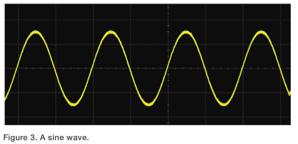
- Sine waves are continuous waves that have a smooth periodic oscillation. For example, alternating currents such as a home’s electrical outlets generate sine waves.
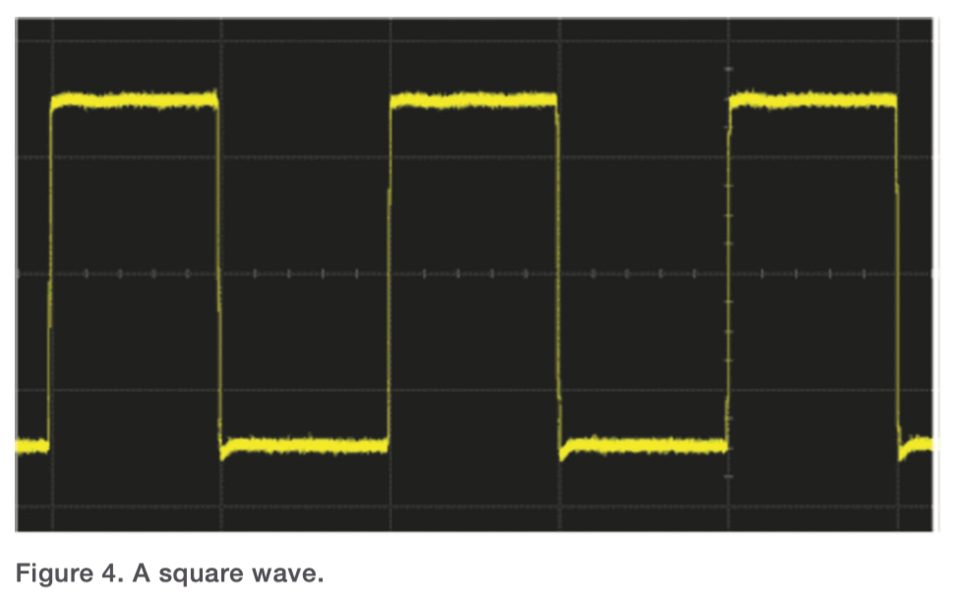
- Rectangular waves periodically jump between a high and a low value, forming edges rather than curves. If the segments’ lengths are equal, the waveform is called square.
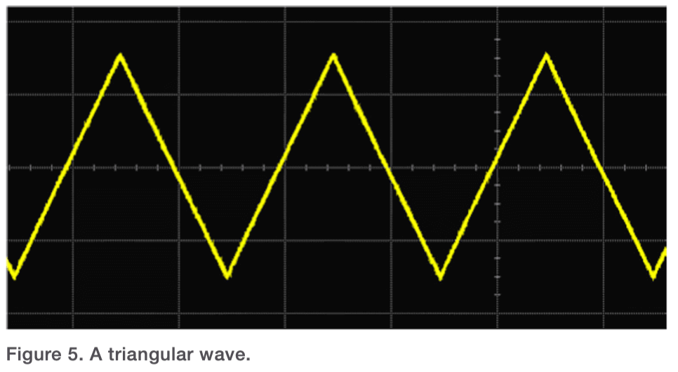
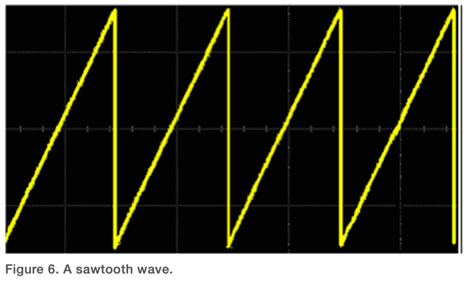
- Triangular waves alsohave linear edges, also called ramps, rising or dropping to a specific voltage level. In sawtooth waves, one edge has a sudden rise or drop that is almost vertical.
- A voltage level that is otherwise constant but shows an abrupt single rise and fall, similar to a light flashing, is a pulse. A pulse train describes a series of such pulses. Pulses often indicate errors or glitches in a signal, but can also occur when the signal carries a singular data point of information.
- Complex waves are mixtures of the wave types mentioned above and others, and are not necessarily periodic.
Another important distinction is the one between analog and digital signals. As an analogy, think of clocks. A digital one displays the time as numbers. Time units are presented as distinct intervals of hours, minutes and seconds, with sudden jumps from one to the next. Correspondingly, digital signals convey quantized, discrete bites of information. The hands on an analog clock, on the other hand, move continuously, without any jumps or discreteness in the reading. Similarly, analog signals are continuous and able to take on any value within some range.
Oscilloscope Basics
With so many brands and types of oscilloscopes available, they might look different from one another, but most have the same set of basic features.
Read the basic introduction on this page or dive into more detail in the Knowledge Base article called Basic Types of Oscilloscopes
Signal Input and Output
By using the input connectors usually located at the front of the oscilloscope, you can connect it to your device under test. It will give you an output in the form of a wave displayed on a screen, either on the oscilloscope itself or a connected computer.
By connecting an oscilloscope to an electronic circuit, it of course becomes an element within the circuit. That is why oscilloscopes are designed to minimize so-called loading effects distorting the signal, so as to preserve signal integrity, or accuracy, as far as possible.
Your oscilloscope can display a whole range of variables as functions. The standard application is rendering a graph, the y-axis being voltage and the x-axis the time. This is especially useful when testing a certain component within the circuit to ascertain if it is behaving as intended. You can compare the signal you are receiving to the waveform the signal should produce. However, instead of plotting one variable over time, you can also use multiple input channels and plot two inputs against each other to compare and analyze them.
Types of Oscilloscopes
Although the very first oscilloscopes developed and used were analog, most of the oscilloscopes sold today are digital, since they offer a wider range of functions and can process more types of signals. Two of the most common types of scopes are DSOs, digital storage oscilloscopes, and MSOs, mixed signal oscilloscopes. DSOs process the analog input of a circuit through an attenuator first – to scale the signal up or down for it to fit into the bandwidth covered – then digitize it, making the information available for a wide range of measurements and indefinite storage. MSOs can monitor, display and trigger on both digital and analog signals all at once.
Some oscilloscopes are designed for a very specific purpose. Handheld or portable scopes are especially lightweight and user friendly. The very best performance capabilities available come in the form of high-performance oscilloscopes. Their update and sampling rates are fast, bandwidth availability is high, they feature considerable memory depth and measurement capabilities that vastly exceed standard specifications, overall making them uniquely suitable for complex projects. On the other end of the spectrum, economy scopes offer best value for money and make a useful measuring tool available to more modest budgets. A good quality oscilloscope will perform accurate measurements for many years, which is why used and refurbished scopes are an excellent alternative to buying new, especially when working with budget restraints.
How Triggering Works
The trigger decides the time window during which the input signal is captured, i.e. when to record information. It allows you to capture a transient event and make accurate measurements by providing a display of the waveform that is both stable and usable.
For example, you could set the trigger for when a falling or rising edge crosses a threshold voltage value. This is called edge triggering and is one of the most popular triggering modes. Glitch triggering allows for triggering on an event or pulse whose width is greater than or less than some specified length of time. This capability is very useful for finding random glitches or errors that may appear infrequently. Many other triggering modes events can be set, depending on the measurement goals.
Read on in this article: Oscilloscopes and triggering explained.
Controls and Measurements
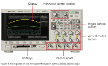
If you are working with an oscilloscope for the first time, the sheer number of controls can be overwhelming and their labels a little cryptic. Even if you have worked with oscilloscopes before, changing models can mean you have to reacquaint yourself with your new tool’s specific functions. In the following section, you will get a brief overview of some basic controls almost every oscilloscope will have and measurements it will be able to perform. Depending on the model, you can control your oscilloscope by hooking it up to your computer, via a built-in touch screen, or, most commonly, simply by using the front-panel buttons.
Vertical Controls
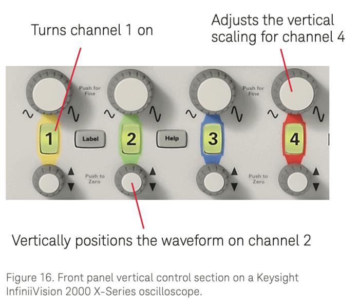
As the name implies, these controls let you control the display’s vertical aspects. Two main features are the scaling factor and positioning. The scaling control lets you set the amount of volts/division on the display grid’s y-axis. In other words, reducing the volts/division allows you to zoom in and increasing it means zooming out. The position of the displayed wave is determined by the vertical offset, which can translate it up or down on the grid. Additionally, the buttons to turn input channels off and on are sometimes located among the vertical controls as well.
Horizontal Controls
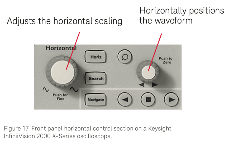
The horizontal axis is handled through these controls. Similar to the vertical controls discussed above, decreasing the time/division – this time on the x-axis – enables you to zoom in on a more specific point of time within your waveform. The offset, or horizontal delay, allows you to move a waveform back and forth in terms of time.
Trigger Controls
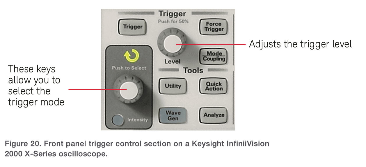
Using these controls, you can set the trigger mode as well as specify the event to trigger on, such as a certain pulse width, polarity, rising or falling edge etc., depending on the mode. You also can set the coupling of the trigger (AC or DC) and which input source to trigger on. For example, you can set a trigger on another signal, related to the one you are sampling and analyzing.
A separate button enables you to adjust the horizontal position of the trigger. Setting a horizontal delay of zero places your trigger to the center of your screen, bringing what occurred before and after the event into view. This is especially useful if you are analyzing glitches and need information on what might have caused them.
Input controls
Oscilloscopes usually have either two analog channels available or four of them, with additional digital channels if your scope is an MSO. The channels are numbered and have individual buttons that enable you to activate or deactivate each particular channel. You should also have the option to set coupling to AC or DC as well as the impedance of the probe, again, individually for each channel.
Using the controls located in the input sections, you can also specify the sampling types you want to execute, with two fundamental ways available: Real-time sampling can render a waveform in a single acquisition by capturing enough individual sample points to create a complete depiction in one sweep. Equivalent time sampling only works for repetitive signals, as it develops the image over several iterations of acquisition. After sampling different parts of the signal on subsequent acquisitions, it then recreates the waveform by piecing the individual samples together. If you are working with signals in the high frequency range, i.e. above 32 GHz, these will be too fast to process in real time and equivalent time sampling will be the best method to use.
Basic measurements
Once you have acquired your waveform, digital oscilloscopes allow you to perform a broad range of different measurements. While their availability and complexity depend on the exact features your new or used oscilloscope has, usually, the most common measurement options listed conveniently on the display.
Here are some basic measurements you can perform with your oscilloscope.
- Period and frequency: These measurements calculate the period and frequency of a signal’s waveform – check in section “Waves and Signals Explained” above for a refresher.
- RMS voltage: The root mean square voltage of your waveform is an average of its amplitude, on the base of which you can in turn calculate the power.
- Peak-to-peak voltage: A measurement of the difference in voltage between the lowest and highest point of a waveform’s cycle.
- Risetime: This measures the time needed for a signal’s voltage to go from a low to a high level. Instead of relying on the absolute peak, it is usually computed by starting at 10% and then calculating how long the signal takes to go to 90% of the above-mentioned peak-to-peak.
- Pulse width: The measurement of a pulse’s width starts at the 50% mark of the voltage (peak-to-peak), then computes how long the signal takes to rise or fall to its minimum or maximum voltage and go back to 50%.
This brief overview is far from comprehensive as most oscilloscopes, used or new, have many more measurement capabilities available in their feature set. In addition, you can use your scope for a wide range of mathematical operations based on your measurements via pre-programmed functions.
Performance Properties
The properties of your scope fundamentally determine its performance in terms of accuracy and reliability when testing devices. By acquainting yourself with the basic properties, you are equipped to decide which oscilloscope suits the project and intended usage best, including whether a new or used scope is the right one for you. Read this in more detail in the Article 6 Performance Characteristics to Look for in an Oscilloscope.
Bandwidth
This has to be the most important aspect of an oscilloscope, as it determines the available frequency range. Only with sufficient bandwidth will your oscilloscope be able to render the signal accurately – it is simply impossible for a scope to display signal outside its available range correctly. Bandwidth is measured in Hertz.
Channels
The independent input connectors on your oscilloscope are referred to as channels, which can vary between only two and as many as twenty, with two or four channels being the most common. Channels can also carry varying types of signals. Some oscilloscopes, for example DSOs, only provide analog channels. MSOs can connect both digital and analog channels.
Sample rate
The number of samples the scope can capture per second is called the sample rate. As a rule of thumb, your oscilloscope’s sample rate should be at least 2.5 times more than the bandwidth, ideally 3 times its bandwidth or even greater. If you are using a scope with a sample rate that is too low for your device under test (DUT), the signal displayed will be distorted, possibly severely so. On specification sheets, manufacturers will usually list the maximum sample rate of an oscilloscope. However, this maximum capacity can sometimes only be reached when the use of channels is limited to one or two, so check carefully how many channels you can use while still maintaining the specified maximum sample rate.
Memory depth
The ADC (analog-to-digital converter) is an integral part of a digital oscilloscope as it digitizes the analog input waveform, with the digitized data then being stored. This is where memory depth becomes important. It limits how many data points or samples can be stored at once. This also makes memory depth an important factor regarding the scope’s sampling rate. The more memory depth is available, the longer the oscilloscope can maintain maximum sampling speed while capturing waveforms.
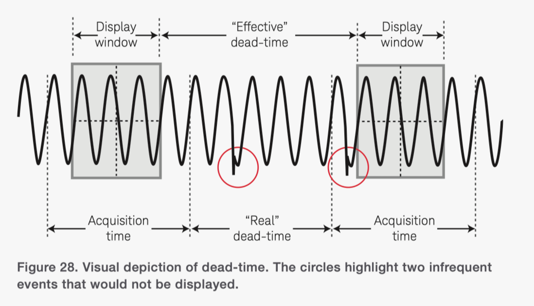
Update rate
How fast an oscilloscope can collect data points and therefore update the waveform on display is determined by the update rate. An oscilloscope creates the illusion that the display of the waveform is happening in real time, but acquisitions of a waveform are really performed at intervals, in between which falls dead time. This means you miss part of the waveform, and should a glitch, error or otherwise infrequent event occur during this dead time, it will not be displayed on the oscilloscope. Dead-times can be shortened through higher update rates, which improves the odds of catching such transient and infrequent events. Maximum update rates may only be available in specific acquisition modes, which can limit your oscilloscope’s performance considerably. Therefore, read update rate specifications with care.
Connectivity features
Oscilloscopes can come with different connectivity options. Whether it is external monitor ports and hard drives, USB ports or other features, they all make completing tasks easier by saving time and allowing for smooth transfers of data. Some oscilloscopes can even be operated remotely via a PC. Considering the large impact these aspects have on work processes, it would be a mistake to underestimate the importance and value of good connectivity features.
Oscilloscope Probes
Your oscilloscope would be incomplete without probes, since these are what connects your scope to the DUT. The nature and quality of your probes influences how accurate the display measurements and analysis of your signal ends up being. Probes really are crucial regarding the integrity of the signal, so you have to choose carefully so as to not limit the capabilities of your scope.
Now for a quick overview of three basic probe types.
- Passive probes make do without an internal power supply as they feature only components that are, as the name says, passive. Signals with bandwidths under 600 MHz can be covered well by these probes. They are rugged and usually inexpensive while being user-friendly, accurate and versatile.
- Active probes are required for signals with bandwidths above 600 MHz. Since they contain active components, they do need to be supplied with power. They are sometimes supported through a cable with USB connector, or by the scopes’ mainframe itself. These active components can condition or amplify a signal as well as cover larger signal bandwidths, which is why they are often used for high-performance devices and circuits. Due to the active components, this type of probe is often pricier than a passive probe. It also tends to be more sensitive to damage and carry a heavier probe tip. However, these probes do allow testing of signals at considerably higher frequencies and minimize capacitive and resistive loading as far as possible.
- Using your scope, current probes can measure a circuit’s current. They are usually big and cover only a limited bandwidth of up to 100 MHz.
Many more types of probes, and probe accessories (such as varying types of probe tips) are available to choose from, dependent entirely on your intended measurements and the characteristics of your DUT. Further reading: How to select the right probes for your oscilloscope.
Before you go
This short overview was intended to give you a head start on basic oscilloscope fundamentals, but of course there is much more to learn. If you are eager to try putting your knowledge into practice, have a look at our latest deals on used Keysight oscilloscopes. Whether its bandwidth or sample rates, they often have better specs at lower prices than new models have to offer. Check out the Keysight Used Equipment Platform to find quality scopes with great quality and savings for you.
Explore Used Keysight Oscilloscopes
Keysight Used offers a wide range of industry leading pre-owned oscilloscopes, ranging from older generation Agilent oscilloscopes to the newest Keysight oscilloscope models. So whether you are a first time buyer, replacing a model like-for-like or looking to upgrade – we have something for you.


