- Introduction
- TL;DR
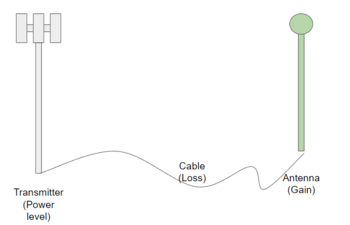
- Definition of EIRP
- Understanding EIRP and Its Impact on Signal Power
- The Basics of EIRP
- Understanding Path Loss and Its Effect on Signal Power
- Signal Power and Mismatch Loss
- Loss in Decibels (dB) and Return Loss Measurement
- EIRP and Path Loss in Antennas and Signal Generators
- Glossary of Terms
- Why Choose Keysight for Your Wireless Communication Needs
- Whenever You’re Ready, Here Are 5 Ways We Can Help You
- Popular Used Oscilloscopes
TL;DR
- EIRP (Effective Isotropic Radiated Power): A critical measure in wireless communication, it represents the maximum power an antenna can radiate in a particular direction.
- Path Loss & Free-Space Path Loss: Essential factors in wireless communication, representing the reduction in signal power over distance. An understanding of path loss is necessary to estimate signal power at the receiver end accurately.
- Mismatch Loss & Return Loss: Both can significantly impact signal power and overall system efficiency. Engineers aim to minimize mismatch loss and maximize return loss for optimal system performance.
- Application in Antennas and Signal Generators: EIRP and path loss are important in designing and operating antennas and signal generators. They affect the coverage, signal strength, and efficiency of power usage.
Definition of EIRP
Did you know? EIRP is so integral in wireless communications that a miscalculation can significantly reduce a system's performance and lead to costly inefficiencies. Effective Isotropic Radiated Power, or EIRP, is a fundamental measure that electrical engineers use to estimate the strength of a radio frequency (RF) signal being transmitted from an antenna. This measure is essential as it encapsulates not only the power supplied to the antenna but also the antenna's ability to convert this power into a signal that propagates in the desired direction.
When working with wireless communication systems, understanding EIRP is pivotal. It's used in a variety of applications, including, but not limited to:
- Cellular networks
- Broadcasting systems
- Satellite communications
- Radar systems
- WiFi networks
An accurate calculation of EIRP can help ensure your communication system's optimal performance, maximum coverage, and efficient power utilization.
In the following sections, we will dive deeper into the components of EIRP and provide a step-by-step guide on how to calculate it. Stay tuned and empower yourself with this key piece of knowledge that can make a real difference in the world of wireless communications.
Understanding EIRP and Its Impact on Signal Power
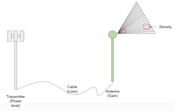
At the core of wireless signal transmission and electrical engineering lies the concept of EIRP. It's a measure of the maximum amount of power that can be radiated from an antenna in a specific direction. When power is measured in an environment where power density is the same in all directions, it helps engineers determine the effectiveness of their power transmission systems.
The Basics of EIRP
Let's break down the concept a bit more. Power density, in simple terms, is the amount of power per unit area. For radio signals, it's the power in an electromagnetic wave per unit area perpendicular to the direction of propagation. An isotropic radiator is a theoretical antenna that radiates power equally in all directions. While no actual antenna can achieve this perfect isotropy, it serves as a baseline for calculations and comparisons.
EIRP is a measure that considers the power supplied to the antenna and its ability to convert this power into a signal that goes in the desired direction. In a way, it can be understood as the power density you'd measure at a specific point if your antenna were an isotropic radiator.
This relationship between power density, isotropic radiators, and EIRP is vital. EIRP allows you to estimate the power radiated in the direction of maximum gain from the antenna, providing a composite measure of system efficiency.
| Key Takeaway |
|---|
| EIRP is a fundamental concept in signal transmission, used to analyze the efficiency of power transfer in wireless systems. It bridges the gap between theoretical isotropic radiators and actual antennas, providing an actionable measure of system efficiency and signal power. |
Understanding Path Loss and Its Effect on Signal Power
Path loss is another key concept in the field of wireless communication. It refers to the reduction in power density that a radio wave undergoes as it propagates through space. The further the signal travels, the more it spreads out, and the less power it has when it reaches its destination. This reduction in power density over distance is the essence of path loss.
Free-space path loss (FSPL) is a specific type of path loss. It represents the loss in signal power that occurs when the signal spreads out in a vacuum or in an open outdoor environment with no other obstacles.
So, how do path loss and EIRP relate? Well, EIRP represents the power that an antenna would radiate in the direction of maximum gain if it were an isotropic radiator. In contrast, path loss signifies the reduction in this radiated power as it propagates through space. Thus, when you know the EIRP of a system and the path loss it experiences, you can determine the power density at any point in the path of propagation.
Understanding the effects of free-space path loss on signal power is crucial in wireless communication. As the signal travels from the transmitter to the receiver, path loss diminishes its power. If the path loss is too great, the receiver might not be able to detect the signal above the noise level. Therefore, engineers use EIRP and path loss to ensure that the signal power will be adequate at the receiving end.
| Key Takeaway |
|---|
| By understanding path loss and its relationship with EIRP, you can accurately estimate signal power at the receiver end and thus improve the efficiency and reliability of wireless systems. This understanding allows for optimized system design, ensuring effective signal transmission over the required distance. |
Signal Power and Mismatch Loss
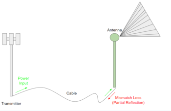
Mismatch loss happens when there is a mismatch between the transmission line (like a coaxial cable or waveguide) and its load (like an antenna or amplifier). Impedance, in simple terms, is the opposition a circuit presents to the flow of current when a voltage is applied.
When the impedance of the load doesn't match the impedance of the transmission line, some of the power will be reflected back towards the source rather than being fully absorbed by the load. This reflection reduces the amount of power available to the load, causing a "mismatch loss" in signal power.
The effects of mismatch loss can be quite substantial in RF systems. If not accounted for, it can lead to inefficient power transfer, potential damage to the transmitter, and a significant reduction in the signal quality at the receiver end.
To minimize mismatch loss in signal transmission, follow these steps:
- Proper Impedance Matching: Carefully design your system so that the impedance of the load matches the impedance of the transmission line. Use matching networks or circuits if necessary.
- Quality Components: Use high-quality transmission lines, connectors, and antennas, which are less likely to introduce impedance mismatches.
- Regular System Checks: Regularly test and monitor your system for any changes in impedance. Unexpected changes can indicate issues such as damage to components or connections.
- System Optimization: Continually optimize your system as new technologies and techniques become available. This can include better matching circuits, more advanced components, or updated design methodologies.
Remember, understanding and managing mismatch loss is key to maintaining high signal power and overall system efficiency. It's another tool in your toolkit to ensure your RF system performs at its best.
Loss in Decibels (dB) and Return Loss Measurement
In the realm of RF systems, return loss is another crucial parameter. It is defined as the loss of power in the signal returned or reflected by a discontinuity in a transmission line or optical fiber. The lower the loss value the better. This discontinuity could be caused by an impedance mismatch, as we discussed earlier. Return loss is a measure of how well a system is matched and is expressed in decibels (dB).
The higher the return loss value, the lower the reflection and the better the impedance match – and, consequently, the better your system performs. For instance, a return loss of 20 dB is better than one of 10 dB.
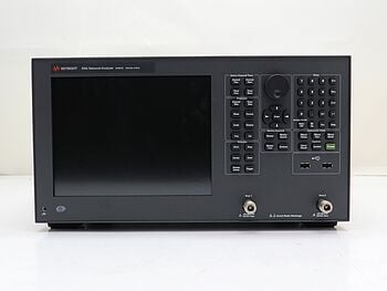
When measuring return loss, several tools and methods come into play. Network analyzers, reflectometers, and specialized return loss meters are typically used to provide precise and accurate measurements.
| Tools for Measuring Return Loss | Accuracy |
|---|---|
| Network Analyzer | High |
| Reflectometer | High |
| Return Loss Meter | Medium |
Network analyzers and reflectometers offer high accuracy and can provide a wealth of information about the characteristics of the transmission line and the load. On the other hand, a return loss meter is a more simplified device specifically designed to measure return loss. It may not provide the same detailed information as a network analyzer or reflectometer, but it can give fast and trustworthy measurements, which makes it great for regular checks and field use.
Choose the tool according to the needs of the application and required level of detail, since each has its strengths and appropriate use cases. By mastering these tools and the concept of return loss, you can effectively manage and optimize your RF system's performance.
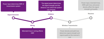
EIRP and Path Loss in Antennas and Signal Generators
The concepts of EIRP and path loss find critical applications in the design and operation of antennas and signal generators, two fundamental elements in any wireless communication system.
EIRP is a decisive measure that informs the design process in antennas. Engineers must consider the gain of the antenna (its ability to direct power in a specific direction) along with the power supplied to it. The EIRP effectively helps optimize the antenna design to achieve desired coverage, signal strength, and efficiency of power usage.
Path loss, on the other hand, is a crucial parameter when setting up communication links. It helps determine the maximum feasible distance between the transmitter (or signal generator) and receiver. Understanding path loss will help you adjust the power of the signal generator. This ensures that the signal can travel the necessary distance, even with path loss, while still maintaining a good signal-to-noise ratio at the receiver.
| Key Takeaway |
|---|
| Understanding and accurately applying EIRP and path loss concepts play a significant role in optimizing the performance of antennas and signal generators. This knowledge allows engineers to maximize coverage, maintain signal strength, and enhance overall system efficiency, making these concepts invaluable in the field of wireless communications. |
Glossary of Terms
| Term | Definition |
|---|---|
| EIRP (Effective Isotropic Radiated Power) | A measure of the maximum amount of power that an antenna can radiate in a specific direction. It's a combination of the power supplied to the antenna and the antenna's ability to radiate this power. |
| Power Density | The amount of power per unit area. For radio signals, it's the power in an electromagnetic wave per unit area perpendicular to the direction of propagation. |
| Isotropic Radiator | A theoretical antenna that radiates power equally in all directions. It serves as a baseline for calculations and comparisons. |
| Path Loss | The reduction in power density that a radio wave undergoes as it propagates through space. |
| Free-Space Path Loss (FSPL) | The loss in signal power that results when a signal spreads out in a vacuum or in an open outdoor environment where no other factors affect the signal. |
| Mismatch Loss | Loss that occurs when there is an impedance mismatch between a transmission line and its load, causing some of the power to be reflected back towards the source. |
| Return Loss | A measure of how well a system is matched, indicating the loss of power in the signal returned or reflected by a discontinuity in a transmission line or optical fiber. |
| Decibel (dB) | A logarithmic unit used to express the ratio of one value of a power or field quantity to another. |
| Antenna Gain | The degree to which an antenna can direct input power into radiation in a specified direction |
| Signal-to-Noise Ratio (SNR) | A measure that compares the level of a desired signal to the level of background noise. It is an important factor in the design of wireless communication systems. |
Why Choose Keysight for Your Wireless Communication Needs
Choosing Keysight for your wireless communication needs comes with numerous benefits:
- Superior Quality and Reliability: Keysight is recognized for its industry-leading tools and services that deliver high-quality results. Their products are tested rigorously for reliability, ensuring optimal performance and longevity.
- Innovative Solutions: With a strong focus on research and development, Keysight offers innovative solutions that keep pace with the fast-evolving wireless communication technology landscape.
- Comprehensive Product Range: Whether you need network analyzers, oscilloscopes, signal generators, or software for design and simulation, Keysight provides a wide array of tools to cater to your needs.
- Excellent Customer Support: Keysight offers expert technical support and customer service to guide you in selecting the right tools, troubleshooting any issues, and maximizing the utility of the products.
By choosing Keysight, you're not just opting for a product or a service; you're partnering with a world-leading technology company that's committed to empowering your wireless communication endeavors.

Whenever You’re Ready, Here Are 5 Ways We Can Help You
- Browse our Premium Used Network Analyzers, Oscilloscopes, Signal Analyzers and Waveform Generators
- Call tech support US: 1 800 829-4444 Press #, then 2. Hours: 7 am – 5 pm MT, Mon– Fri
- Talk to our sales support team by clicking the icon (bottom right corner) on every offer page.
- Create an account to get price alerts and access to exclusive waitlists
- Talk to your account manager about your specific needs.
Popular Used Oscilloscopes
Keysight Used Oscilloscopes offers a wide range of industry leading pre-owened oscilloscopes, ranging from older generation Agilent oscilloscopes to the newest Keysight oscilloscope models. So whether you are a fist time buyer, replacing a model like-for-like or looking for upgrade – we have something for you.