- Introduction
- Power Factor Calculator: An Essential Guide for Electrical Engineers
- TL;DR
- Understanding Power Factor and Its Impact on Electrical Systems
- The Basics of Power Factor
- Power Factor in Real-World Applications
- Power Factor Correction: Enhancing Efficiency in Electrical Systems
- Understanding Power Factor Correction
- Power Factor Correction Capacitor's Capacitance Calculation
- Glossary of Terms
- Why Choose Keysight for Your Wireless Communication Needs
- Whenever You’re Ready, Here Are 5 Ways We Can Help You
- Popular Used Oscilloscopes
Did you know that understanding the concept of power factor can lead to significant cost savings, energy efficiency, and longer equipment life in the field of electrical engineering? It's a little-understood principle, yet it holds substantial importance in electrical systems, impacting everything from your monthly energy bill to the lifespan of your equipment.
Power factor is a critical measure of how effectively incoming power is converted into useful output power, or in other words, how efficiently your electrical system is functioning. When we delve into the realm of alternating current circuits, power factor emerges as a pivotal player in determining the efficiency of power consumption.
Imagine you are tasked with designing an industrial power system, or perhaps, diagnosing electrical problems in a complex network. Wouldn't it be beneficial to predict the power loss and identify ways to mitigate it? Here's where power factor calculations can help.
TL;DR
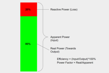
- Power factor is a critical concept in electrical engineering, representing the effectiveness of power usage in a system. It's calculated as the ratio of real power to apparent power.
- Power factor correction, often achieved by using capacitors, is a technique that adjusts the power factor closer to 1, enhancing system efficiency and leading to cost and energy savings.
- Correct calculation of the capacitance of power factor correction capacitors plays a key role in optimizing electrical system performance.
- Understanding and applying the concepts of power factor and power factor correction are crucial for solving common challenges in electrical engineering, such as energy waste and system inefficiencies.
Understanding Power Factor and Its Impact on Electrical Systems
It's a crucial component whose impact stretches across the entire fabric of electrical systems. In essence, the power factor is a key player in shaping the efficiency, reliability, and sustainability of power networks. So let's dive deeper into this principle and understand how it truly operates.
The Basics of Power Factor
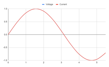
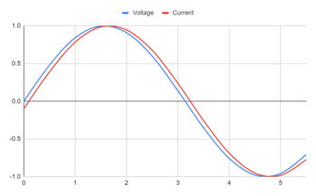
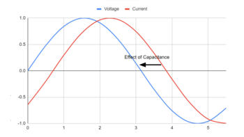
Power factor, symbolized as PF, is a dimensionless number between -1 and 1. In an AC circuit, the power factor is determined by calculating the cosine of the angle formed by the current and voltage. In other words, it's a measure of how "in phase" the current and voltage are with each other. A power factor of 1 indicates perfect synchronization, where the current and voltage rise and fall together. This scenario is ideal as it means there's no wasted power.
| Parameter | Formula |
|---|---|
| Power Factor | Real Power (W) / Apparent Power (VA) |
Power Factor in Real-World Applications
While the theory behind power factor is fascinating, its application in real-world scenarios is where it truly shines. One of the most important applications of this technology is in the field of three-phase circuits, which are commonly found in industrial and commercial electrical systems.
For instance, motors in industrial applications often create a lagging power factor. This can lead to inefficiencies and increased energy costs. By correcting the power factor, engineers can ensure these systems run more efficiently, reducing energy costs and waste.
Another real-world application is in the operation of fluorescent lights and LED drivers. These devices can have a power factor less than 1, which means they're not using the power provided to them as efficiently as possible. Power factor correction can help improve the efficiency of these devices.
Moreover, power factor is crucial in determining the sizing of cables, switchgear, and generators in electrical system design. A lower power factor can result in higher current, leading to larger and more expensive equipment and higher installation costs.
Now, let's see how we can calculate power factor in a three-phase circuit:
- Measure the voltage (V) across the load
- Measure the current (I) through the load
- Determine the real power (P) in watts
- Calculate the apparent power (S) using the formula: S = √3 * V * I
- Calculate the power factor using the formula: PF = P / S
By understanding and applying the concept of power factor in such situations, electrical engineers can optimize system performance, reduce energy consumption, and save on costs.
| Key Takeaway |
|---|
| Power factor is not just a theoretical concept, but a practical tool that, when properly understood and applied, can help solve common challenges in electrical engineering. It plays a vital role in improving the efficiency of electrical systems, thereby leading to energy conservation and cost savings. |
Power Factor Correction: Enhancing Efficiency in Electrical Systems
Power Factor Correction (PFC) is the secret weapon behind the efficient operation of every electrical system. This process is an essential strategy as it boosts the effectiveness of power consumption, leading to a sustainable and economical electrical system.
Understanding Power Factor Correction
Power factor correction is a technique used to bring the power factor of an electrical system closer to 1, which is the ideal power factor. This is achieved by compensating for the reactive power in the system, hence minimizing wasted power and enhancing the efficiency of power utilization.
Notably, power factor correction can be beneficial in several ways.
- It can help reduce energy costs, as a higher power factor reduces the amount of wasted energy.
- It contributes to more efficient energy usage, reducing the demand on the power grid.
- Power factor correction can extend the lifespan of electrical components, as it reduces the heat and strain on the equipment due to inefficiencies.
The steps to correct the power factor in electrical systems include:
- Measure the existing power factor in the electrical system.
- Identify the loads causing a lower power factor (usually inductive loads like motors or transformers).
- To counteract the effects of inductive or capacitive loads, install capacitors or inductors. Decide whether to place them at the load or at the distribution panel based on whether the current lags or leads the voltage.
- Monitor the power factor after installing the correction equipment to ensure it is closer to 1.
| Key Takeaway |
|---|
| Power factor correction is a practical and crucial technique that plays an indispensable role in enhancing electrical system efficiency. By correcting the power factor, electrical engineers can not only make energy consumption more efficient but also contribute to extending the lifespan of the system's components. |
Power Factor Correction Capacitor's Capacitance Calculation
The use of capacitors is one of the most common methods for correcting power factors in electrical systems. These devices work by compensating for the lagging or leading current in inductive loads, effectively increasing the power factor. The value of capacitance required for effective power factor correction is crucial, as it determines the ability of the capacitor to store and release electrical energy.
To calculate the capacitance needed for power factor correction, use the formula:
| Parameter | Formula |
| Capacitance (F) | Reactive Power (VA) / (2 * \(\pi\) * Frequency (Hz) * Voltage^2)= \(\frac{Q}{2\pi FV^2}\) |
Reactive Power (Var) is the power that oscillates between the source and load, which doesn't perform any real work. Frequency (Hz) is the rate at which current changes direction per second. Voltage (V) is the electrical potential difference between two points in a circuit.
Calculating the correct capacitance for power factor correction is essential for system optimization. Using a capacitor with the correct size not only enhances the power factor, but it also boosts energy efficiency and promotes the durability of the electrical components.
Glossary of Terms
Below is a quick-reference glossary of key terms associated with power factor and power factor correction:
| Term | Definition |
|---|---|
| Power Factor (PF) | A measure of how effectively electrical power is being used in a system. It's calculated as the ratio of Real Power to Apparent Power. A PF of 1 indicates optimal efficiency. |
| Real Power (P) | The actual power (in watts) that's doing the work in an electrical circuit. Also known as active power. |
| Apparent Power (S) | The total power (in volt-amperes) in an AC circuit, both working power (real) and reactive power. It's calculated as the product of the current and voltage in the circuit. |
| Reactive Power (Q) | The power (in volt-amperes reactive, or VA) that oscillates between the source and load, which doesn't perform any real work but is necessary for the functioning of AC circuits. |
| Power Factor Correction (PFC) | A technique used to bring the power factor of an electrical system closer to 1, thereby making the system more efficient. |
| Inductive Load | An electrical load that causes current to lag behind voltage because it uses the current to create a magnetic field. Examples include motors and transformers. |
| Capacitive Load | An electrical load where the current leads the voltage because it stores the electrical energy. Examples include capacitors. |
| Capacitance (C) | The ability of a component to store an electric charge. It's used in power factor correction to compensate for the lagging current in inductive loads. |

Why Choose Keysight for Your Wireless Communication Needs
Keysight Technologies offers innovative solutions for wireless communication that bring unparalleled value to engineers worldwide. Here are some key benefits of choosing Keysight for your wireless communication needs:
- Cutting-Edge Technology: Keysight is consistently at the forefront of technological advancements, offering state-of-the-art tools and services that keep you ahead of the curve in the fast-evolving wireless communication industry.
- Comprehensive Product Range: Whether you need network analyzers, oscilloscopes, signal generators, or software, Keysight provides a wide array of equipment for all your needs.
- Excellent Customer Support: Keysight offers expert technical support and customer service to guide you in selecting the right tools, troubleshooting any issues, and maximizing the utility of the products.
Choosing Keysight means choosing a partner dedicated to providing top-tier solutions and support in the wireless communication sector.

Whenever You’re Ready, Here Are 5 Ways We Can Help You
- Browse our premium refurbished network analyzers, oscilloscopes, signal analyzers and waveform generators.
- Call tech support US: 1 800 829-4444 Press #, then 2 Hours: 7am – 5pm MT, Mon– Fri
- Talk to our sales support team by clicking the icon (bottom right corner) on every offer page
- Create an account to get price alerts and access to exclusive waitlists
- Talk to your account manager about your specific needs
Popular Used Oscilloscopes
Keysight Used Oscilloscopes offers a wide range of industry leading pre-owened oscilloscopes, ranging from older generation Agilent oscilloscopes to the newest Keysight oscilloscope models. So whether you are a fist time buyer, replacing a model like-for-like or looking for upgrade – we have something for you.