- Introduction
- Parallel Resistor Calculator & An Essential Guide for Electrical Engineers
- TL;DR
- Understanding Parallel Resistance and Its Role in Circuit Design
- Calculating Parallel Resistance: A Step-by-Step Guide
- Applications of Parallel Resistance in Circuit Design
- Using Oscilloscopes and Signal Generators in Resistance Measurement
- Glossary of Terms
- Why Choose Keysight for Your Wireless Communication Needs
- Whenever You’re Ready, Here Are 5 Ways We Can Help You
- Popular Used Oscilloscopes
"In the realm of electrical engineering, understanding the behavior of parallel resistors is not optional, it's a necessity. Mastering this can redefine your approach to circuit design and, by extension, pave the way for breakthrough innovations," – Dr. Robert L. Boylestad, renowned author of 'Introductory Circuit Analysis.'
When you grapple with the concept of parallel resistors, you're not simply crunching numbers or going through the motions of a theoretical exercise. Instead, you're unlocking the potential to design more efficient circuits, develop advanced electronic systems, and enhance the functionality of countless devices.
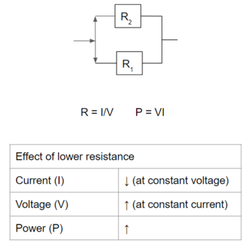
In a parallel circuit, resistors share the same voltage across them, a property that differs significantly from a series circuit. This unique behavior results in the total resistance of the circuit being lower than the smallest resistor in the parallel configuration. The ability to manipulate resistance values in this manner is crucial in various applications such as voltage division, impedance matching, and signal processing.
However, calculations of parallel resistance can often be challenging due to the complexity of the formula, especially when there are more than two resistors in the circuit. Therefore, to assist you, we have put together this guide to help you navigate parallel resistance calculations. So how do you accurately calculate the total resistance in a parallel resistor circuit? Let's look at the equations and a practical example to illustrate the process.
TL;DR
- Understanding Parallel Resistance: Parallel resistance is fundamental to electrical engineering, playing a pivotal role in power distribution, voltage management, and circuit protection. The total resistance decreases as more resistors are added in a parallel circuit.
- Calculating Parallel Resistance: To calculate the total resistance of resistors in parallel, sum up the reciprocals of individual resistors and take the reciprocal of the result. Mastering this calculation is essential for efficient circuit design.
- Applications in Circuit Design: Parallel resistors are used widely in power distribution, voltage management, amplifier circuits, and digital logic circuits, impacting performance and functionality significantly.
- Measuring Resistance: Tools like oscilloscopes and signal generators are used to measure resistance in real-world applications. They help visualize voltage changes that can be used to calculate resistance based on Ohm's law.
Understanding Parallel Resistance and Its Role in Circuit Design
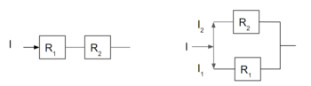
Parallel resistors, as the name suggests, are resistors that are connected side by side in a circuit. This arrangement allows the current to have multiple paths to travel. It's a fundamental concept in electrical engineering as it allows us to manage and control how current is distributed in a circuit.
The total resistance in a parallel circuit, often surprising to those new to the field, decreases as more resistors are added. This is because adding more resistors provides additional paths for the current to travel, effectively lessening the total resistance in the circuit.
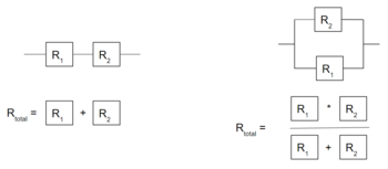
To calculate the total resistance of two resistors in parallel, you can use the formula:
| Total Resistance (Rt) | Formula |
|---|---|
| For 2 Resistors | \(R_{t} = (R_{1} * R_{2}) / (R_{1} + R_{2})\) |
| For n Resistors | \(1/R_{t}= 1/R_{1} + 1/R_{2} + ... + 1/R_{n}\) |
It's essential to note that when calculating the total resistance of more than two resistors in parallel, the formula changes. You need to calculate the reciprocal of each resistance, sum them up, and then take the reciprocal of the result to get the total resistance. The formula for a system with two resistors is a special case, where a simplified formula is useful.
The role of parallel resistors in circuit design is vast and crucial. They are used to distribute power across different devices or components, manage voltage levels, and protect components from excessive current. The efficient use of parallel resistors can significantly enhance the performance and reliability of an electrical system.
Calculating Parallel Resistance: A Step-by-Step Guide
To calculate the total resistance of resistors in parallel, use the following formula:
\(1/R_{t}= 1/R_{1} + 1/R_{2} + ... + 1/R_{n}\)
To calculate total resistance:
- Write down the formula for calculating total parallel resistance.
- Calculate the reciprocal of each resistance.
- Sum up the values obtained in the previous step.
- Calculate the reciprocal of the result to get the total resistance.
Let's illustrate how to calculate parallel resistance using a real-world example. Imagine an electrical circuit with three resistors in parallel, having resistance values of 5 ohms, 10 ohms, and 15 ohms.
| Step | Calculation | Result |
|---|---|---|
| 1 | (Write down the formula) | \(1/R_{t}= 1/R_{1} + 1/R_{2} + 1/R_{3}\) |
| 2 | 1/5, 1/10, 1/15 | 0.2, 0.1, 0.0667 |
| 3 | 0.2 + 0.1 + 0.0667 | 0.3667 |
| 4 | 1/0.3667 | 2.73 Ohms |
| Key Takeaway |
|---|
| Calculating parallel resistance may seem a bit complicated at first, but it's straightforward once you understand the formula. It's a critical skill for electrical engineers, allowing them to design efficient and safe electrical systems. The key is remembering that in a parallel circuit, the total resistance will always be less than the smallest individual resistance. |
Applications of Parallel Resistance in Circuit Design
Parallel resistors are a core component in numerous electrical engineering scenarios. They are integral to managing voltage levels, power distribution, and circuit protection, all of which have a profound impact on circuit performance and functionality.
Let's explore some situations where parallel resistance calculations play a key role:
1. Power Distribution: In a parallel circuit, each resistor has its path for current, which makes it possible to evenly distribute power across multiple components. This uniform distribution ensures that each device gets the power it requires for optimal functionality.
2. Voltage Management: In parallel circuits, voltage remains constant across all resistors. This characteristic is advantageous in scenarios where we need to maintain a constant voltage across multiple components or devices, such as in a home electric system.
3. Circuit Protection: By using parallel resistors, you can safeguard sensitive components from excessive current. The total resistance decreases in parallel circuits, thus allowing a lower current flow through without harming the individual elements.
4. Amplifier Circuits: In audio systems and signal processing, parallel resistors are vital in amplifier circuits. They help control gain and impedance, critical for sound quality and consistency.
5. Pull-Up and Pull-Down Resistors: In digital electronics, parallel resistors are used as pull-up and pull-down resistors. They define the voltage level for logic gates when no input is present, thus enabling the representation of binary values.
Key application areas of parallel resistance in circuit design include:
- Power distribution systems
- Voltage management in various electronic devices
- Circuit protection in sensitive electronic devices
- Amplifier circuits in audio systems and signal processing
- Pull-up and pull-down resistors in digital logic circuits
Understanding parallel resistance and its calculations is pivotal for designing efficient and reliable circuits. It allows electrical engineers to harness the power of electricity safely and effectively, optimizing the performance of many devices and systems we rely on daily.
Using Oscilloscopes and Signal Generators in Resistance Measurement
Oscilloscopes and signal generators are invaluable tools in an electrical engineer's toolbox, playing a pivotal role in measuring resistance, including parallel resistance. They help visualize the changes in signal voltages, which can be used to calculate resistance based on Ohm's law (V=IR).
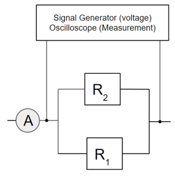
The signal generator is used to create a known voltage or current across the resistors, while an oscilloscope can measure the voltage over the resistor and the current flowing through it.

Let's break down the process of using these tools to measure resistance, particularly parallel resistance:
- Connect the signal generator across the parallel resistors. Set it to generate a known, steady (DC) voltage.
- Use the oscilloscope to measure the voltage across the resistors, connecting the probe to the same points as the signal generator. This is your 'V' in Ohm's law.
- Now, measure the current flowing through the resistors. If an ammeter isn't embedded in your setup, use a known series resistor and measure the voltage drop across it. Apply Ohm's law to find the current. This is your 'I' in Ohm's law.
- Use Ohm's law (V=IR) to calculate the resistance, R=V/I.
Remember to follow safe practices when using these instruments. Always ensure devices are properly grounded and remember to switch off and disconnect the power supply before adjusting the circuit.
| Key Takeaway |
|---|
| Oscilloscopes and signal generators are essential for measuring resistance in real-world applications. They provide a hands-on approach to understanding and verifying your calculations, reinforcing your grasp of parallel resistance and how it behaves in actual circuits. |
Glossary of Terms
| Term | Definition |
|---|---|
| Parallel Circuit | A circuit where the components are connected side by side, providing multiple paths for the current to flow. |
| Resistor | A component used in circuits to restrict the flow of electric current. |
| Resistance | A property that quantifies how strongly a given material opposes the flow of electric current. |
| Ohm's Law | A fundamental principle in electronics that states the voltage across a conductor is proportional to the current flowing through it. The constant of proportionality is the resistance. |
| Pull-up Resistor | A resistor used to ensure that a wire is pulled to a high logical level in the absence of an input signal. |
| Pull-down Resistor | A resistor used to ensure that a wire is pulled to a low logical level in the absence of an input signal. |
| Amplifier Circuit | An electronic device or circuit that increases the power of a signal. |

Why Choose Keysight for Your Wireless Communication Needs
Choosing Keysight's tools and services for your wireless communication needs brings several benefits:
- Innovation: Keysight is known for its cutting-edge, high-quality equipment that enables efficient design and testing.
- Reliability: With a reputation built over decades, Keysight delivers dependable and accurate results in every tool and service offered.
- Comprehensive Solutions: Keysight provides end-to-end solutions for all wireless communication needs, from design simulation to validation, testing, and optimization.
- Expert Support: Keysight offers unparalleled technical support and guidance, assisting you at every step of your project.

Whenever You’re Ready, Here Are 5 Ways We Can Help You
- Browse our premium refurbished network analyzers, oscilloscopes, signal analyzers and waveform generators.
- Call tech support US: 1 800 829-4444 Press #, then 2. Hours: 7 am – 5 pm MT, Mon– Fri
- Talk to our sales support team by clicking the icon (bottom right corner) on every offer page.
- Create an account to get price alerts and access to exclusive waitlists
- Talk to your account manager about your specific needs.
Popular Used Oscilloscopes
Keysight Used Oscilloscopes offers a wide range of industry leading pre-owened oscilloscopes, ranging from older generation Agilent oscilloscopes to the newest Keysight oscilloscope models. So whether you are a fist time buyer, replacing a model like-for-like or looking for upgrade – we have something for you.