- Introduction
- Amplification Methods
- Active Amplification
- Passive Amplification
- Find Used Function Generators On Sale
- Choosing the Right Amplification Method
- Amplification Circuit Design
- Components Needed
- Circuit Design Process
- Selecting the Right Components for Your Amplification Circuit
- Maintaining Signal Integrity in Amplification
- Troubleshooting
- Troubleshooting Checklist:
- Expert Insights on Signal Amplification
- Elevate Your Test and Measurement Experience with Keysight Function Generators and Amplification Solutions
- Key Takeaways
- Closing Thoughts From Keysight
- Whenever You’re Ready, Here Are 4 Ways We Can Help You
- Great Deals: Function Generators On Sale Right Now
As an electrical engineer, you've undoubtedly encountered the challenge of choosing a device that not only delivers accurate and reliable results, but also offers the flexibility to adapt to a variety of testing scenarios. This pursuit of accuracy is a shared experience among professionals in the field, often centering on the pivotal role of the function generator.
A function generator is a type of signal generator that is specifically designed to generate various types of waveforms, such as sine, square, and triangular waves, to stimulate, test, or troubleshoot circuits.
Understanding the importance of signal amplification and techniques to achieve it is crucial for any engineer looking to enhance their projects' performance. In the following sections, we'll delve deeper into the methods and best practices for amplifying the signal from a function generator, empowering you to confidently tackle any signal-related challenges.
Amplification Methods
To successfully amplify the signal output from a function generator or waveform generator, it's essential to understand the two main methods of amplification: active and passive. Each method has unique characteristics, advantages, and disadvantages.
Active Amplification
Active amplification involves the use of active components, such as operational amplifiers (Op-Amps) or transistor amplifiers, to boost the signal. These active elements require an external power source to function and can provide significant signal gain.
Operational Amplifier (Op-Amp): Op-Amps are versatile and widely used integrated circuits that amplify, buffer, or filter signals. They provide high input impedance, low output impedance and can deliver significant voltage or current gain. Op-Amps are ideal for a variety of applications, including audio and instrumentation amplifiers.
Transistor Amplifier: Transistor amplifiers use bipolar junction transistors (BJTs) or field-effect transistors (FETs) to amplify the input signal. They can be configured in common emitter, common collector, or common base configurations, each offering distinct characteristics and performance parameters. Transistor amplifiers are popular in radio frequency (RF) and high-frequency applications.
Advantages of active amplification include high gain, low output impedance, and improved signal-to-noise ratio. However, these amplifiers may introduce distortion, require an external power source, and can be more complex to design and implement.
Passive Amplification
Passive amplification, on the other hand, relies on passive components like resistors, capacitors, and transformers to transfer energy from one part of a circuit to another. Passive amplifiers do not require an external power source and typically provide less gain than their active counterparts.
Resistor-Capacitor(RC) Coupling: RC coupling uses a combination of resistors and capacitors to transfer AC signals from one stage to another while blocking DC components. This method is often employed in audio frequency and low-frequency applications due to its low cost, simplicity, and effective filtering capabilities.
Transformer Coupling: Transformer coupling uses transformers to transfer signals between different stages of a circuit. This method provides electrical isolation and impedance matching, making it well-suited for high-frequency applications such as radio and communication systems.
Passive amplification offers advantages like simplicity, lower cost, and no need for an external power source. However, it typically provides lower gain, and the performance may be affected by component values and tolerances.
When choosing between active and passive amplification methods, it's essential to consider factors like gain requirements, power availability, frequency range, and the specific application in which the amplifier will be used. By carefully evaluating these factors, you can select the most suitable amplification method for your function generator signal.
Find Used Function Generators On Sale


Choosing the Right Amplification Method
When deciding on the most suitable amplification method for your function generator signal, it's crucial to consider several factors that can impact the performance and compatibility of the amplifier with your specific application. Input and output impedance, gain, and bandwidth are key factors that will influence your choice between active and passive amplification methods.
Input and Output Impedance: Impedance is the opposition to the flow of current in a circuit, and it plays a significant role in determining the efficiency and effectiveness of signal transfer between stages. Matching the input impedance of the amplifier with the output impedance of the function generator will ensure maximum power transfer and minimize signal loss.
Active amplifiers typically offer high input impedance and low output impedance, making them well-suited for a broad range of applications. Passive amplifiers, however, may require additional impedance-matching components.
Gain: Gain is the ratio of the output signal strength to the input signal strength, and it is a crucial factor when determining the required amplification level. Active amplifiers generally provide higher gain than passive amplifiers, making them ideal for applications where substantial signal boosting is required. If your application demands only a minimal increase in signal strength or requires signal conditioning without amplification, a passive amplifier may be the better choice.
Bandwidth: Bandwidth is the range of frequencies over which the amplifier can operate effectively. The bandwidth requirements of your application will significantly influence the choice of amplification method. Active amplifiers can provide a wide bandwidth, suitable for various applications, while passive amplifiers, such as transformer-coupled designs, may have a more limited frequency range. It's essential to choose an amplifier with a bandwidth that matches or exceeds the requirements of your specific application.
To choose the appropriate amplification method for your function generator signal, begin by evaluating the requirements of your application in terms of input and output impedance, gain, and bandwidth. Consider the advantages and disadvantages of both active and passive amplification methods, and assess their suitability for your particular project.
Active amplifiers are generally more versatile and provide higher gain, making them suitable for various applications. However, if simplicity, lower cost, or the absence of an external power source is a priority, passive amplifiers may be a better fit.
By carefully analyzing these factors and understanding their implications, you'll be better equipped to select the most suitable amplification method for your function generator signal, ensuring optimal performance and reliable results in your projects.
Amplification Circuit Design
Designing an amplification circuit can be a rewarding experience, as it allows you to tailor the circuit to your specific requirements. This section will provide a step-by-step guide to help you design an amplification circuit, covering the essential components and design process.
Components Needed
To design an amplification circuit, you'll need the following components.
| Amplifier | The amplifier is the primary active component in the circuit, responsible for increasing the signal strength. Depending on your application, you may choose an operational amplifier (Op-Amp), a transistor amplifier (BJT or FET), or another suitable device. |
|---|---|
| Power Supply | The power supply provides the necessary voltage and current to the active components in the circuit. For Op-Amps, you may need a dual power supply (positive and negative voltage rails). Transistor amplifiers typically require a single power supply. |
| Input and Output Coupling Capacitors | These capacitors are used to separate the AC signal from the DC bias voltage, preventing any DC voltage from being transferred between stages. The capacitors' values should be chosen to provide a low-impedance path for the signal frequencies of interest. |
| Biasing Resistors | Biasing resistors set the operating point for the amplifier and ensures it operates in the correct region (e.g., linear region for Op-Amps, active region for transistors). The values of these resistors will depend on the specific amplifier and desired operating point. |
Circuit Design Process
The circuit design process involves determining the circuit configuration, calculating the component values, and assembling the circuit. Here's a step-by-step guide to designing an amplification circuit:
- Determine the circuit configuration: Choose the type of amplifier (Op-Amp or transistor) and the specific configuration (inverting, non-inverting, or differential for Op-Amps, common emitter, common collector, or common base for transistors) based on your application requirements, such as gain, input and output impedance, and bandwidth.
- Calculate component values: Using the chosen amplifier's datasheet and the desired operating parameters (gain, input and output impedance, and bandwidth), calculate the values of the resistors and capacitors required for the circuit. For Op-Amps, you'll need to calculate the feedback resistor (Rf) and input resistor (Ri) values. For transistor amplifiers, you'll need to calculate the biasing resistor (Rb) values and the emitter resistor (Re) value, if applicable.
- Assemble the circuit: With the component values determined, assemble the circuit on a breadboard or other prototyping platform. Ensure proper connections are made, and double-check the polarities of components, such as electrolytic capacitors and transistors.
- Test the circuit: Power up the circuit and test its performance using a function generator and an oscilloscope. Adjust component values if necessary to achieve the desired gain, bandwidth, and input/output impedance.
- Finalize the design: Once the circuit meets your performance requirements, create a schematic and, if necessary, design a printed circuit board (PCB) for the final implementation.
By following this guide, you can design a custom amplification circuit that meets your specific needs, ensuring optimal performance and reliability in your engineering projects.
Selecting the Right Components for Your Amplification Circuit
Choosing the appropriate components for your amplification circuit is crucial for achieving optimal performance and ensuring reliable and accurate test results. The specific application, signal frequency range, and required gain are all critical factors to consider when selecting components. Here, we'll provide guidance on how to choose the right components for your amplification circuit.
Type of Amplifier: The choice of amplifier depends on factors such as the signal frequency range, required gain, input and output impedance, and power supply constraints. For low-to-moderate frequency applications with a wide bandwidth and high gain, operational amplifiers (Op-Amps) are an excellent choice. For radio frequency (RF) and high-frequency applications, transistor amplifiers (BJTs or FETs) are more suitable. Ensure you select an amplifier with the appropriate specifications for your particular application.
Input and Output Coupling Capacitors: Coupling capacitors separate the AC signal from the DC bias voltage, preventing any DC voltage from being transferred between stages. When selecting coupling capacitors, consider the following:
- a. Capacitance: Choose capacitors with a capacitance value that provides a low impedance path for the signal frequencies of interest. A general rule of thumb is to select a capacitor with a reactance (Xc) that is at most one-tenth of the input or output impedance at the lowest frequency of interest. The reactance can be calculated using the formula Xc = 1/(2πfC), where f is the frequency and C is the capacitance.
- b. Voltage Rating: Ensure the capacitors have a voltage rating that exceeds the maximum voltage they will be exposed to in the circuit. This rating should include any potential transient voltage spikes or fluctuations in the power supply.
Biasing Resistors: Biasing resistors set the operating point for the amplifier and ensure it operates in the correct region (linear region for Op-Amps, active region for transistors). When selecting biasing resistors, consider the following:
- a. Tolerance: Choose resistors with an appropriate tolerance for your application. A tighter tolerance (e.g., 1% or 0.1%) ensures more precise component values and improved circuit performance.
- b. Power Rating: Select resistors with a power rating that can handle the power dissipation within the circuit. This rating should be at least twice the expected power dissipation to ensure long-term reliability.
Power Supply: Choose a power supply that can provide the required voltage and current levels for your amplifier. For Op-Amps, you may need a dual power supply (positive and negative voltage rails). Transistor amplifiers typically require a single power supply. Ensure the power supply has sufficient current capacity and voltage regulation for your specific application.
By carefully considering your specific application requirements and selecting the appropriate components, you can ensure reliable and accurate test results from your amplification circuit. Always consult datasheets and reference designs for guidance, and don't hesitate to iterate and fine-tune your component selections to optimize your circuit's performance.
Maintaining Signal Integrity in Amplification
Signal integrity plays a critical role in amplification circuits, as it ensures the amplified output accurately represents the input signal without distortion or degradation. Preserving signal integrity is especially important for engineers working with high-frequency signals or those new to signal amplification.
In this section, we'll provide guidance on measuring and improving signal integrity in an amplification circuit through a series of tips and best practices.
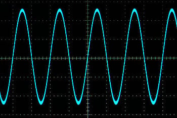
- Measure Signal Integrity: Use an oscilloscope to monitor the input and output signals of your amplification circuit. Look for any signs of distortion, noise, or signal degradation, such as ringing, overshoot, or undershoot. Additionally, use a spectrum analyzer to assess the harmonic content and noise within the signal's frequency domain.
- Choose the Right Components: Select amplifiers and passive components that are appropriate for the frequency range and signal characteristics of your application. Ensure the chosen components have adequate bandwidth, gain, and noise performance to maintain signal integrity.
- Proper Power Supply Decoupling: To reduce power supply noise and ensure stable operation, use proper decoupling techniques. Place decoupling capacitors close to the power supply pins of the amplifier, and use a combination of low-value (e.g., 100nF) and high-value (e.g., 10µF) capacitors to cover a wide frequency range.
- Minimize Parasitic Components: Parasitic inductance and capacitance can degrade signal integrity, especially in high-frequency applications. To minimize these effects, use a compact circuit layout, minimize trace lengths, and avoid sharp corners. Choose components with low parasitic inductance and capacitance, such as surface-mount devices (SMDs).
- Impedance Matching: Ensure proper impedance matching between the amplifier's input and output and the connected devices or circuits. Impedance mismatches can result in signal reflections, which can cause distortion and signal degradation. To achieve optimal signal transfer, use impedance matching techniques, such as resistive pads, transformers, or matching networks.
- Grounding and Shielding: Implement proper grounding techniques, such as a single-point ground or a ground plane, to minimize ground loop noise and electromagnetic interference (EMI). Use shielding techniques, such as shielded cables or enclosures, to protect sensitive signals from external noise sources.
- Minimize Temperature Effects: Temperature fluctuations can affect component performance and signal integrity. Design your circuit with components that have stable performance over the expected temperature range, and consider using temperature compensation techniques, such as temperature-stable resistors or temperature compensation networks, to maintain consistent performance.
- Test and Debug: Continuously monitor your circuit's performance during the design and testing phases. Identify potential signal integrity issues and implement improvements. Be prepared to adjust component values, circuit layouts, or design techniques to optimize signal integrity.
By following these tips and best practices, engineers new to signal amplification or those working with high-frequency signals can ensure their amplification circuits maintain signal integrity, resulting in accurate and reliable test results.
Troubleshooting
Amplifying the signal from a function generator can sometimes introduce challenges, such as noise, oscillation, and distortion. In this section, we'll discuss common problems that can arise when amplifying a signal and provide a
| Noise | Noise can manifest as random fluctuations in the signal, which can be caused by various sources, such as power supply noise, thermal noise, or electromagnetic interference (EMI). |
|---|---|
| Oscillation | Unwanted oscillations in the output signal can be caused by feedback in the amplification circuit, leading to instability and potentially damaging the amplifier or connected devices. |
| Distortion | Distortion occurs when the output signal deviates from the input signal, altering its shape or amplitude. This can result from nonlinear amplifier behavior, saturation, or clipping. |
Troubleshooting Checklist:
- Check Power Supply: Ensure the power supply is stable, clean, and within the specified voltage range for your amplifier. Add decoupling capacitors close to the amplifier's power supply pins to filter out high-frequency noise.
- Verify Component Connections: Double-check all component connections, ensuring proper orientation and placement. Verify that there are no loose connections, short circuits, or damaged components.
- Examine Circuit Layout: Inspect the circuit layout for potential issues, such as long traces, sharp corners, or inadequate grounding. Minimize parasitic inductance and capacitance by using compact layouts and short traces.
- Test Input Signal: Verify that the input signal from the function generator is within the expected range and free from distortion or noise. Ensure the function generator is set to the correct frequency, amplitude, and waveform.
- Assess Amplifier Stability: Check the amplifier's stability by verifying the phase and gain margins. Adjust the feedback network or add compensation components to improve stability and prevent oscillation.
- Monitor Temperature: Ensure that the circuit is operating within the specified temperature range for all components. Check for hot spots or temperature-related performance issues, and implement temperature compensation techniques if necessary.
- Review Impedance Matching: Verify proper impedance matching between the amplifier and connected devices. Adjust the impedance-matching network or use a different amplifier configuration to achieve optimal signal transfer.
- Inspect Grounding and Shielding: Confirm that proper grounding techniques are implemented, such as single-point ground or ground planes. Use shielded cables or enclosures to protect sensitive signals from external noise sources.
- Analyze Output Signal: Monitor the output signal with an oscilloscope and a spectrum analyzer, checking for noise, oscillation, or distortion. Adjust component values, circuit layouts, or design techniques to improve signal integrity.
By following this troubleshooting checklist, engineers can systematically diagnose and resolve common problems that arise when amplifying signals from a function generator. Remember that iterative testing and adjustment are essential in optimizing circuit performance and ensuring reliable, accurate results.
Expert Insights on Signal Amplification
To provide you with a deeper understanding and different perspectives on signal amplification, here are some quotes and insights from industry experts, researchers, and experienced engineers.
- Drs. Howard Johnson and Martin Graham, authors of "High-Speed Digital Design: A Handbook of Black Magic":
"When dealing with high-speed signals, it is essential to carefully match the impedance of the transmission line to the source and load impedances, as impedance mismatches can lead to signal reflections and degrade signal integrity."
Source: High-Speed Digital Design: A Handbook of Black Magic - Bob Pease, a legendary analog engineer and author of "Troubleshooting Analog Circuits":
"When you're trying to amplify a signal, you need to understand not only the gain but also the frequency response, noise, and distortion characteristics of the amplifier. A well-designed amplifier should be able to deliver the desired performance without sacrificing signal integrity."
Source: Troubleshooting Analog Circuits
Elevate Your Test and Measurement Experience with Keysight Function Generators and Amplification Solutions
Upgrade your signal amplification setup with our state-of-the-art function and waveform generators along with high-quality components from Keysight Technologies. Browse our extensive catalog of function generators and amplification products to find the perfect fit for your engineering projects. Ensure accuracy, reliability, and high performance for all your test and measurement needs. Don't miss out on our special discounts – shop now and elevate your engineering projects to new heights!
Key Takeaways
In this article, we covered various aspects of signal amplification from a function generator, including
- The importance of amplifying signals from function generators to meet specific engineering requirements.
- The main methods of amplification, active and passive, along with their advantages and disadvantages.
- Factors to consider when choosing the right amplification method, such as input and output impedance, gain, and bandwidth.
- A detailed guide on designing amplification circuits, selecting the right components, and ensuring signal integrity.
- Tips and best practices for troubleshooting common problems in amplification circuits, such as noise, oscillation, and distortion.
- Expert insights from industry professionals on signal amplification and its crucial role in achieving accurate and reliable test results.
Closing Thoughts From Keysight
In this comprehensive guide, we have delved into the intricacies of signal amplification from function generators, discussing various methods, circuit design, component selection, troubleshooting, and expert insights. Understanding these concepts is vital for engineers striving to achieve accurate and reliable test results in their projects.
At Keysight Technologies, we are committed to providing cutting-edge tools and components that make reliable test results accessible and affordable for engineers worldwide. By leveraging our extensive catalog of high-quality function generators, amplification solutions, and expert knowledge, you can elevate your test and measurement projects to new heights. We take pride in being your trusted partner in engineering excellence, ensuring you have the support and resources to overcome challenges and succeed.
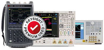
Explore our selection of Used and Premium Used Equipment and find the perfect fit. Shop at Keysight and see why we are a leading supplier of waveform generators, function generators, and signal generators.

Whenever You’re Ready, Here Are 4 Ways We Can Help You
- Browse our Premium Function and Waveform Generators.
- Call tech support US: 1 800 829-4444
Press #, then 2. Hours: 7am – 5pm MT, Mon– Fri - Talk to our sales support team by clicking the icon (bottom right corner) on every offer page
- Talk to your account manager about your specific needs