- Introduction
- Understanding Impedance
- What Is Impedance and Why Is It Called Z?
- What Is the Impedance Symbol and Formula?
- Types of Impedance
- Impedance in RLC Circuits
- Formula of Impedance in RLC Circuits
- Calculating inductive and capacitive reactance (XL and XC)
- The Impedance Triangle and Its Significance
- Key Takeaways
- Impedance Formulas and Calculations
- Simple Formula for Impedance
- Calculating Impedance in Series and Parallel Circuits
- Using polar and cartesian forms for impedance calculations
- Key Takeaways
- Impedance Matching and Its Importance
- Why Do We Calculate Impedance?
- Impedance Matching in PCB Design and Transmission Lines
- Key Takeaways
- Practical Applications of Impedance
- How Impedance Affects Voltage and Current Flow in Circuits
- What Is the Impedance of a Voltage Output?
- SI Units for Impedance and Their Significance
- Key Takeaways
- Conclusion
- Unlock the Full Potential of Impedance and Network Analysis with Keysight Technologies
- Closing Thoughts From Keysight
- Whenever You’re Ready, Here Are 4 Ways We Can Help You
In the dynamic field of electrical engineering, the accurate calculation of impedance is paramount to optimizing the performance of a wide array of circuit boards and systems. As the measure of opposition to the flow of electrical current, impedance plays a critical role in determining the efficiency and functionality of these systems.
Electrical engineers often face the challenge of precisely calculating impedance to address issues such as signal distortion, power loss, and component stress. This comprehensive impedance formula guide is designed to provide electrical engineers with the tools and knowledge to tackle these problems head-on, ensuring reliable and efficient operation of their designs.
Understanding Impedance
Impedance is a fundamental concept in electrical engineering that represents the opposition to the flow of alternating current (AC) in a circuit. It is a complex quantity, encompassing both the resistive and reactive components of an electrical circuit.
What Is Impedance and Why Is It Called Z?
Using the letter Z helps distinguish impedance from other electrical quantities like resistance (R) and reactance (X), which are the components of impedance. The letter Z was chosen because it signifies the last letter of the alphabet, reflecting the idea that impedance encompasses the complete opposition to electrical current in a circuit, including both resistive and reactive components.
What Is the Impedance Symbol and Formula?
The symbol for impedance is Z, and its formula combines both resistive (R) and reactive (X) components in a complex manner. The general impedance formula is as follows:
Z = R + jX
In this formula, R represents the resistance, X signifies the reactance, and j is the imaginary unit (j^2 = -1).
Types of Impedance
Impedance can be categorized into three main types: resistive, reactive, and complex impedance. Each type represents a specific aspect of opposition to electrical current in a circuit.
- Resistive Impedance (R): This type of impedance is associated with resistors and other components that generate heat when current passes through them. In the ideal case it is purely real, meaning it has no imaginary component and is frequency-independent.
- Reactive Impedance (X): Reactive impedance is associated with reactive components, such as capacitors and inductors, which store and release energy in the form of electric and magnetic fields. Reactive impedance is purely imaginary, meaning it has no real component and is frequency-dependent. It is further divided into capacitive reactance (XC) and inductive reactance (XL).
- Complex Impedance (Z): Complex impedance is a combination of both resistive and reactive impedance, reflecting the total opposition to electrical current in a circuit. It is expressed as a complex number, with real and imaginary parts representing resistance and reactance, respectively. Complex impedance is frequency-dependent and is used to analyze AC circuits with a combination of resistive and reactive components.

Impedance in RLC Circuits
In RLC circuits, which consist of resistors (R), inductors (L), and capacitors (C), impedance plays a crucial role in determining the opposition to alternating current (AC). Impedance in RLC circuits combines resistance, inductive reactance, and capacitive reactance, accounting for the complex interactions between these components in the presence of AC signals. By understanding and calculating impedance in RLC circuits, engineers can effectively analyze, design, and optimize various electrical systems and components, ensuring optimal performance and efficiency.
Formula of Impedance in RLC Circuits
In RLC circuits, which include resistors (R), inductors (L), and capacitors (C), the impedance formula combines resistance, inductive reactance, and capacitive reactance:
Z = R + j(XL + XC)
Calculating inductive and capacitive reactance (XL and XC)
The formulas for calculating inductive reactance (XL) and capacitive reactance (XC) are as follows:
Inductive reactance formula: XL = 2πfL, where f is the frequency and L is the inductance.
Capacitive reactance formula: XC = -1/(2πfC), where f is the frequency and C is the capacitance.
The Impedance Triangle and Its Significance
The impedance triangle visually represents the relationship between resistance, reactance, and impedance. It is a right triangle, with resistance (R) as the adjacent side, reactance (X) as the opposite side, and impedance (Z) as the hypotenuse. The impedance triangle formula is:
Z^2 = R^2 + X^2
where X = XL + XC.
Key Takeaways
Understanding impedance in RLC circuits is crucial for electrical engineers working with AC circuits, as it enables them to analyze and optimize the performance of various components and systems. By mastering the impedance formula and the formulas for inductive and capacitive reactance, engineers can effectively calculate and control the opposition to current flow in a circuit.
The impedance triangle serves as a valuable visualization tool to comprehend the relationship between resistance, reactance, and impedance, ultimately facilitating better circuit design and analysis in practical applications.

Impedance Formulas and Calculations
As electrical engineers navigate the complexities of circuit design and analysis, a thorough understanding of impedance formulas and calculations is essential. These mathematical tools allow engineers to assess the behavior of circuits and components, allowing for optimization of performance and efficiency in a wide range of applications.
Simple Formula for Impedance
The simplified impedance formula, which combines resistance (R) and reactance (X) as a complex number, is:
Z = R + jX
Calculating Impedance in Series and Parallel Circuits
Key steps for calculating impedance in both series and parallel circuits are as follows:
Series Circuits:
- Add resistances directly: Rtotal = R1 + R2 + ...
- Add inductive reactances directly: XL_total = XL1 + XL2 + ...
- Add capacitive reactances directly: XC_total = XC1 + XC2 + ...
- Calculate the net reactance: Xtotal = XL_total – XC_total
- Apply the simplified impedance formula: Ztotal = Rtotal + jXtotal
Parallel Circuits:
- Calculate the reciprocal of each impedance: 1/Zn = 1/(Rn + jXn)
- Sum the reciprocals: 1/Ztotal = Σ(1/Zn)
- Find the reciprocal of the sum to obtain the total impedance: Ztotal = 1/(Σ(1/Zn))
Impedance formulas for series and parallel circuits are:
- Series circuits: Ztotal = Rtotal + jXtotal
- Parallel circuits: Ztotal = 1/(Σ(1/Zn))
Using polar and cartesian forms for impedance calculations
Impedance calculations can be performed using either polar or cartesian forms. In the polar form, impedance is represented by its magnitude and phase angle (Z = |Z|∠θ), while in the cartesian form, it is expressed as a complex number with real and imaginary parts (Z = R + jX). Both forms can be used interchangeably, depending on the specific requirements of the calculation or analysis.
Key Takeaways
Understanding and applying impedance formulas is essential for electrical engineers, as these calculations provide valuable insights into the behavior of circuits and their components. By mastering impedance calculations for series and parallel circuits, engineers can effectively analyze and optimize the performance of electrical systems. Familiarity with polar and cartesian impedance forms offers flexibility in tackling various circuit analysis problems and enhances the engineer's ability to address real-world challenges.

Impedance Matching and Its Importance
In the realm of electrical engineering, impedance matching plays a critical role in ensuring efficient energy transfer between components, circuits, and systems. By understanding the importance of impedance matching, engineers can optimize system performance, minimize signal loss, and prevent issues arising from mismatched impedance.
Why Do We Calculate Impedance?
Calculating impedance is essential for several reasons:
- To analyze and understand the behavior of circuits and components under different conditions.
- To optimize the power transfer between components or systems, such as antennas, amplifiers, and transmission lines.
- To minimize signal loss and distortion in communication systems and high-speed data transmission.
- To prevent undesirable effects like reflections, standing waves, and overheating caused by mismatched impedance.
Impedance Matching in PCB Design and Transmission Lines
Impedance matching is crucial in PCB design and transmission lines to ensure efficient energy transfer and signal integrity. PCB traces and transmission lines have characteristic impedance, and the impedance of components and devices must match this value to prevent reflections and signal loss. Mismatched impedance leads to degraded signal quality, power loss, and electromagnetic interference.
One common technique for impedance matching in PCB design is to use microstrip or stripline transmission lines with specific widths and spacings to achieve a desired impedance. Using vias, ground planes, and shielding can also aid in impedance matching. In transmission lines, impedance matching can be achieved using impedance transformers, such as baluns or quarter-wave transformers.
Key Takeaways
Impedance matching is a crucial aspect of electrical engineering that ensures efficient energy transfer, minimizes signal loss, and prevents issues arising from mismatched impedance. Engineers must master the art of calculating impedance and applying various impedance matching techniques to optimize system performance across diverse applications, including PCB design and transmission lines. By embracing the importance of impedance matching, engineers can tackle real-world challenges and create more efficient and reliable systems.

Practical Applications of Impedance
Impedance plays a pivotal role in electrical engineering, significantly influencing the behavior of circuits and components. In this section, we will explore the impact of impedance on voltage and current flow in circuits, the impedance of voltage output, and delve into the SI units for impedance and their significance. Understanding these practical aspects of impedance enables engineers to design more efficient systems and make informed decisions in their day-to-day work.
How Impedance Affects Voltage and Current Flow in Circuits
Impedance dictates how voltage and current interact in electrical circuits, particularly in AC systems. The presence of resistive and reactive components leads to a complex relationship between voltage and current, governed by Ohm's law for AC circuits: V = IZ, where V is voltage, I is current, and Z is impedance. The phase angle between voltage and current depends on the nature of the impedance, with purely resistive circuits exhibiting no phase difference and circuits with reactive components having phase differences that can impact power factors and system efficiency.
What Is the Impedance of a Voltage Output?
The impedance of a voltage output refers to the output impedance of a device or component, such as an amplifier or power supply. Output impedance is essential because it influences the interaction between the device and the load it drives. Ideally, voltage sources should have low output impedance to minimize voltage drops and ensure maximum power transfer to the load.
SI Units for Impedance and Their Significance
Impedance is measured in SI units called ohms (Ω). Common units related to impedance and their meanings are:
| Unit | Quantity | Meaning |
|---|---|---|
| Ohm (Ω) | Impedance (Z) | The opposition to current flow in a circuit |
| Henry (H) | Inductance (L) | The ability of an inductor to store magnetic energy |
| Farad (F) | Capacitance (C) | The ability of a capacitor to store electrical energy |
| Siemens (S) | Admittance (Y) | The inverse of impedance, representing ease of current flow |
| Hertz (Hz) | Frequency (f) | The rate at which an AC signal oscillates |
Key Takeaways
Impedance is a fundamental concept in electrical engineering, profoundly affecting voltage and current flow in circuits. Understanding the practical implications of impedance, such as output impedance, is crucial for designing efficient and reliable systems. Familiarity with the SI units for impedance and related quantities provides engineers with the necessary tools to quantify and analyze circuit behavior, paving the way for better decision-making and improved performance in real-world applications.
Conclusion
Throughout this comprehensive guide, we have explored the importance of understanding impedance calculations for electrical engineers. Impedance plays a pivotal role in the behavior and performance of electrical circuits and systems, influencing voltage and current flow, power transfer, signal integrity, and overall efficiency.
Mastering impedance calculations and the various formulas associated with series and parallel circuits, as well as impedance matching techniques, empowers engineers to tackle real-world challenges and optimize the performance of their designs. Familiarity with the practical applications of impedance, such as output impedance and its SI units, allows engineers to make informed decisions in their day-to-day work.
As electrical engineers continue to push the boundaries of technology, further exploration of impedance concepts and their practical applications is vital. The knowledge gained from such exploration will undoubtedly contribute to advancements in diverse fields, from communication systems and power electronics to renewable energy and beyond. By delving deeper into the world of impedance, engineers can forge new paths toward more efficient, reliable, and innovative solutions that shape our future.
Unlock the Full Potential of Impedance and Network Analysis with Keysight Technologies
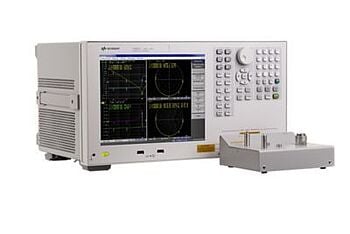
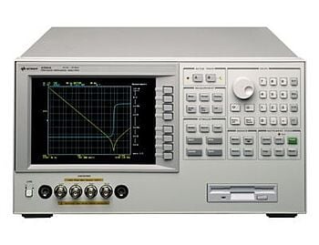
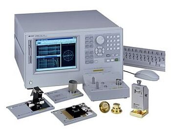
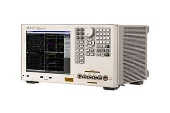
Are you ready to master the intricacies of impedance and network analysis? Look no further than Keysight Technologies, a global leader in electronic testing and measurement solutions. Our comprehensive catalog of impedance analyzers and ENA series network analyzers, combined with our unparalleled industry expertise, will allow you to tackle even the most complex impedance measurements. Explore our huge selection of cutting-edge products and services, and start your journey toward engineering excellence.

Closing Thoughts From Keysight
From our comprehensive exploration of impedance, it's clear that understanding impedance calculations, matching techniques, and their practical applications are essential for electrical engineers. Impedance plays a vital role in the performance and efficiency of circuits and systems, and mastering these concepts paves the way for better decision-making and innovative solutions.
At Keysight Technologies, we strive to make reliable test results accessible and affordable for engineers worldwide. Our cutting-edge products and services enable you to confidently tackle impedance and network analysis challenges, ensuring optimal design performance.
As a trusted partner in your engineering journey, Keysight is committed to empowering you with the knowledge and tools you need to excel in a rapidly evolving technological landscape. Together, we can shape a future where innovative solutions and efficient systems become the norm, driving progress in the world of electronics and beyond.
Explore our selection of Used and Premium Used Equipment and find the perfect fit. Shop at Keysight and see why we are a leading supplier of impedance analyzers, LCR meters, ENA series network analyzers and signal generators for professionals.

Whenever You’re Ready, Here Are 4 Ways We Can Help You
- Browse our Premium impedance analyzers
- Call tech support US: 1 800 829-4444
Press #, then 2. Hours: 7am – 5pm MT, Mon– Fri - Talk to our sales support team by clicking the icon (bottom right corner) on every offer page
- Talk to your account manager about your specific needs