- Introduction
- Applications of Inductance Measurement
- Inductance Measurement: The Theory
- Pros and Cons of Using an Oscilloscope and Signal Generator for Inductance Measurement
- Setting Up the Circuit
- Taking the Measurements
- Troubleshooting Tips
- Check the Connections
- Adjust the Signal Frequency
- Adjust the Signal Amplitude
- Check the Ground Connection
- Check for Noise
- Use a Different Inductor
- Verify the Oscilloscope Settings
- Discover the Benefits of Measuring Inductance With a Keysight Oscilloscope and Signal Generator
- Whenever You’re Ready, Here Are 4 Ways We Can Help You
As an engineer, you know that to understand the behavior of electronic devices and circuits, you have to measure their components accurately. It's like a doctor taking your temperature to help diagnose an illness. Without the thermometer, the doctor can't know what is wrong.
Measuring inductance is no different. It requires special equipment to get an accurate reading. If you don't have the right tools, your results can be skewed, and you risk making the wrong assessment of your circuit.
The good news is that measuring inductance doesn't have to involve complicated equipment. This guide will show you how to measure inductance with a signal generator and oscilloscope. You'll learn the basics of inductance measurement, what equipment you need, and how it works together. Let's get started!
Applications of Inductance Measurement
Measuring inductance is an important aspect of designing and analyzing various electrical components, and it has several applications in multiple industries. Here are a few examples.
- Designing filters. Inductance measurements can design filters used in various circuits to eliminate unwanted noise or signals. By measuring the inductance of the filter components, you can optimize the filter's performance and ensure that it provides the desired attenuation level.
- Designing transformers. Transformers transfer power between circuits and are critical components in many electrical systems. By measuring the inductance of the transformer windings, you can ensure that the transformer is optimized for the intended application and operates at peak efficiency.
- Inductance sensing. You use inductance sensing in various applications, including non-contact position sensing, current sensing, and liquid-level sensing. In these applications, inductance measures the position of a moving object, the amount of current flowing through a conductor, or the level of liquid in a tank.
- Power electronics. Inductors are critical in many power electronics applications, including DC-DC converters and switching power supplies. By measuring the inductance of the inductors, you can optimize the performance of these systems and ensure that they operate efficiently.
- Audio engineering. Inductors are used in many audio circuits, such as filters and equalizers, to shape the system's frequency response. Measuring the inductance of these components can help you optimize the system's performance and ensure that it provides the desired sound quality.
 Step-By-Step Guide: Measuring Inductance with an Oscilloscope and Signal Generator
Download for Free With a Keysight Used Equipment Store Account


Inductance Measurement: The Theory
Inductance is a property of an electrical circuit that describes its ability to create a magnetic field. When an electrical current flows through a conductor, a magnetic field is generated around it.
The strength of the magnetic field depends on the current, the number of turns in the conductor, and the physical characteristics of the conductor itself. Inductance is measured in henrys (H) and is defined as the ratio of the voltage across the inductor to the rate of change of current through it.
You will need the following equipment to measure inductance using an oscilloscope and a signal generator.
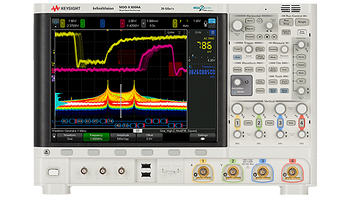
- An oscilloscope measures the voltage waveform produced by the inductor.
- A signal generator supplies an input waveform to the inductor.
- A known reference inductor to calibrate the measurement system. Often it is a standard resistor or capacitor.
- A breadboard or PCB to assemble the circuit. This is the same type of board used in prototyping circuits.
- Leads and probes to connect the various components together.
To measure the inductance, you will need to construct a simple circuit board consisting of the inductor, a capacitor, and a resistor. The signal generator supplies a sinusoidal voltage waveform to the circuit, and the oscilloscope measures the voltage across the inductor.
The basic principle behind this method is that the inductor and capacitor form a resonant circuit with a resonance frequency that is dependent on the inductance value. By measuring the resonant frequency and knowing the capacitor and resistor values, the inductance is calculated using the following formula.
L = 1/(4π²f²C)
Where L is the inductance in henrys, f is the resonance frequency in hertz, and C is the capacitance in farads.
When selecting the appropriate equipment for inductance measurement, it is important to consider the accuracy required and the frequency range of the measured circuit.
LCR meters, network analyzers, and other specialized instruments can provide more accurate and comprehensive inductance measurements over a broader frequency range. However, oscilloscopes and signal generators are cost-effective and much easier to use for measuring inductance in circuits with moderate frequencies.
When looking for equipment to measure inductance, there are a few key features to consider.
- Determine the frequency range of the circuit you need to measure and select equipment with a frequency range that covers this range.
- Consider the required accuracy of your measurements, and choose equipment that meets these requirements. Specialized instruments such as LCR meters and network analyzers provide higher accuracy measurements than oscilloscopes and signal generators.
- Look for equipment with high resolution to accurately capture small changes in the electrical signal.
- Consider the equipment's ease of use and user-friendliness, particularly if you are new to measuring inductance.
- Finally, consider the cost of the equipment and select an option that fits within your budget while still meeting your measurement needs.
When evaluating different options for measuring inductance, consider reading reviews and comparing technical specifications. At Keysight, we offer a wide range of instruments for measuring inductance, from low-cost signal generators and oscilloscopes to advanced network analyzers.
Our Used Equipment provides high-quality, refurbished instruments, all at an affordable price. That means you get the performance, reliability, and quality you need without breaking the bank. Since our Premium Used Equipment is all refurbished, calibrated, and goes through a rigorous 101-point quality check, you can be sure your instruments will be ready to go right out of the box.
Pros and Cons of Using an Oscilloscope and Signal Generator for Inductance Measurement
When it comes to measuring inductance, various methods are available, each with its advantages and limitations. Here is a comparison of using an oscilloscope and signal generator for inductance measurement.
| Pros | Explanation |
|---|---|
| Cost-effective | Oscilloscopes and signal generators are typically less expensive than other specialized equipment, such as LCR meters or network analyzers, making them cost-effective for many engineers. |
| Wide availability | Oscilloscopes and signal generators are widely available, making finding and purchasing equipment easy. |
| Easy to use | Both oscilloscopes and signal generators are relatively easy to use, with intuitive interfaces that allow even novice users to measure inductance. |
| Suitable for moderate frequency applications | Oscilloscopes and signal generators are ideal for measuring inductance in circuits with moderate frequencies, making them suitable for many typical applications. |
| Cons | Explanation |
|---|---|
| Lower accuracy | Oscilloscopes and signal generators have lower accuracy than specialized equipment such as LCR meters or network analyzers. |
| Limited frequency range | Basic oscilloscopes and signal generators have a limited frequency range, making them less suitable for high-frequency applications. |
| More complex calibration | Calibration of the measurement system requires a reference inductor and can be more complicated than other methods. |
| Longer measurement time | Measuring inductance using an oscilloscope and signal generator can be more time-consuming than other methods due to the need for calibration and the longer measurement time. |
Setting Up the Circuit
Let's put into practice the theory of measuring inductance using an oscilloscope and signal generator. Understanding how to set up the circuit correctly is key for accurate measurements. Here is a step-by-step guide for setting up the circuit to measure inductance using an oscilloscope and signal generator.
- Connect the signal generator to the input of the inductor. The input is connected to the output of the signal generator, and the output is connected to the oscilloscope.
- Set the signal generator to output a sine wave signal. The frequency of the sine wave needs to be set to the desired measurement frequency.
- Adjust the voltage amplitude of the signal generator so that the voltage across the inductor is within the range of the oscilloscope. A good rule of thumb is to set the voltage amplitude to around 1-volt peak-to-peak.
- Connect the oscilloscope to the output of the inductor. The oscilloscope should be set to AC coupling so that the DC component of the signal source is removed.
- Adjust the oscilloscope settings to capture the waveform accurately. Set the timebase to capture a few cycles of the sine wave and adjust the vertical scale to capture the full range of the signal.
- Measure the voltage across the inductor using the oscilloscope. The peak-to-peak voltage of the waveform is proportional to the inductance of the circuit.
- Adjust the frequency of the signal generator and repeat steps 3 to 6 to measure inductance at different frequencies.
When adjusting the frequency and amplitude of the signal generator, it is important to remember that the amplitude needs to be set to a level within the range of the oscilloscope. Setting the amplitude too high will distort the signal, making it difficult to measure inductance accurately.
Similarly, setting the frequency too high will also cause the signal to become distorted, so it is essential to stay within the frequency range of the oscilloscope and signal generator.
Taking the Measurements
Now that you know how to set up the circuit, it's time to take some measurements. To measure inductance using an oscilloscope and signal generator, follow these steps:
- Measure the signal voltage across the inductor using the oscilloscope. Set the oscilloscope to measure the peak-to-peak voltage of the waveform.
- Measure the current flowing through the inductor using the signal generator. Set the signal generator to output a known current and connect the inductor in series with the signal generator. Use an ammeter or a current probe to measure the current flowing through the circuit.
- Calculate the inductance of the inductor using the measured voltage and current. The formula for calculating inductance is L = V / (ωI), where L is the inductance in Henrys, V is the peak-to-peak voltage across the inductor, I is the current flowing through the inductor in amps, and ω is the angular plot frequency of the waveform in radians per second. To calculate the angular frequency, use the formula ω = 2πf, where f is the frequency of the waveform in Hertz.
For example, let's say we measure a peak-to-peak voltage of 2 volts across an inductor and a current of 0.5 amps flowing through the inductor at a frequency of 1 kHz. The angular frequency is calculated as ω = 2π1000 = 6283.2 radians per second. Using the formula L = V / (ωI), we can calculate the inductance as L = 2 / (6283.2*0.5) = 6.37*10-4 henrys, or 63.7 microhenrys.


Troubleshooting Tips
It may not be as simple as the above steps make it seem to measure inductance with an oscilloscope and signal generator. It's common to encounter errors, artifacts, and other issues. As an engineer, troubleshooting is part of the job, so it's important to be aware of potential problems and how to address them. Some standard checks and tips to help you can carry out correct inductance measurements include:
- Checking the connections
- Adjusting the signal frequency
- Adjusting the signal amplitude
- Checking the ground connection
- Checking for noise
- Using a different inductor
- Verifying the oscilloscope settings
Check the Connections
One of the easiest and quickest tips is double-checking all connections before taking any measurements. Ensure that the signal generator and oscilloscope are correctly connected to the inductor and that all connections are secure. Loose or incorrect connections will lead to inaccurate readings and damage to your equipment. Taking a few extra moments to check your connections can save time and prevent issues down the line.
Adjust the Signal Frequency
If you're measuring inductance at multiple frequencies, adjust the signal generator's frequency accordingly. It is essential to stay within the range of the oscilloscope and signal generator so that signals do not distort. For low-frequency measurements, a frequency range of 1 Hz to 100 kHz is enough.
You may need to use a higher frequency range, such as 1 MHz to 1 GHz, for higher-frequency measurements. If necessary, use an attenuator or amplifier to reduce the amplitude of high-amplitude signals, which can cause distortion.
Adjust the Signal Amplitude
Adjust the amplitude of the signal generator to ensure that it is within the oscilloscope's dynamic range. Too low an amplitude may lead to inaccurate readings due to noise, while too high an amplitude can cause distortion and incorrect measurements. If necessary, use a voltage divider or attenuator to reduce the signal's voltage.
You should also consider the voltage rating of the measured inductor and ensure that the signal amplitude does not exceed the voltage rating. For example, if measuring a 100V-rated inductor, the signal generator amplitude should not exceed this value.
Check the Ground Connection
Ensuring that the signal generator, oscilloscope, and inductor are properly grounded is crucial for accurate inductance measurements. When the grounding is incorrect, this can result in noisy or distorted readings or even damage to the equipment. Here are some steps you can follow to check the ground connection.
- Check the grounding of the power outlet. Ensure that the power outlet is properly grounded. You can use a plug tester or a multimeter to check the voltage source for proper grounding.
- Check the grounding of the equipment. Ensure that the signal generator and oscilloscope are properly grounded. Most equipment has a grounding lug or screw that can attach a grounding wire. Ensure that the grounding wire is securely attached to the equipment.
- Check the grounding of the inductor. Ensure that the inductor is properly grounded. Some inductors have a ground terminal that you can use for this purpose. You can attach a grounding wire to a nearby metal surface if there is no ground terminal.
If you encounter issues with the ground connection, here are some steps you can follow to fix them.
- Ensure that the grounding wire is securely attached. If the grounding wire is loose or not connected properly, this can result in noisy or distorted readings. Ensure that the wire is securely attached to the equipment and the inductor.
- Use a different power outlet. If the power outlet is not grounded correctly, you should use a different, properly grounded outlet.
- Use a ground loop isolator. If you cannot fix the ground connection issue, you can use a ground loop isolator to eliminate ground loops and improve the quality of the measurements.
Check for Noise
Noise can affect the accuracy of inductance measurements. If you cannot get accurate readings, check for noise in the circuit. Here are some steps you can follow to reduce or eliminate noise.
- Move away from sources of interference. Ensure that your work area is not near any sources of interference, such as power lines, wireless networks, or fluorescent lighting.
- Use shielded cables. Ensure the oscilloscope and signal generator are connected with shielded cables to reduce electromagnetic interference (EMI).
- Use a filter. A low-pass filter can block out high-frequency noise from signals.
- Use an oscilloscope shield. An oscilloscope shield reduces noise and electromagnetic interference from the environment.
Use a Different Inductor
If you are still unable to get accurate inductance measurements, it is possible that the inductor is defective. Check for any visible signs of damage or defects before discarding the inductor.
When selecting an appropriate replacement inductor, it is important to consider the inductance value, current rating, resistance, voltage rating, and temperature range. The inductance value should match the desired circuit design specifications, while the current and voltage ratings should not exceed that of the device being replaced.
Additionally, the resistance of the inductor should be low enough to avoid excessive power loss. Finally, select an inductor with a temperature rating suitable for the operating environment.
Verify the Oscilloscope Settings
Before measuring inductance with an oscilloscope, set the scope parameters correctly. Ensure you use the proper vertical and horizontal scale settings and trigger levels. Additionally, make sure to adjust the gain if necessary.
The voltage scale needs to be set so that the inductor voltage is at one-third of the full-scale deflection. Set the time scale so you can view several signal cycles on the screen.
It is also important to select an appropriate window size for capturing accurate readings. If the window size is too small, it can result in inaccurate measurements. Finally and most importantly, ensure the oscilloscope is calibrated before taking readings.
Once these parameters are set correctly, you can start measuring inductance with your oscilloscope.
Step-By-Step Guide: Measuring Inductance with an Oscilloscope and Signal Generator
Download for Free With a Keysight Used Equipment Store Account
Discover the Benefits of Measuring Inductance With a Keysight Oscilloscope and Signal Generator
As we have seen, measuring inductance with an oscilloscope and signal generator offers many advantages. Using this method, you can accurately measure the inductance of a component in real time. Additionally, you can use this method to troubleshoot complex circuits and optimize system performance.
An oscilloscope and signal generator may be the perfect solution if you are looking for a reliable and accurate way to measure inductance. Try them today and take your circuit testing to the next level!
If you are looking for next-level circuit testing, you will need an oscilloscope and signal generator to handle anything you throw at it. Check out the options available from Keysight today!
We have the perfect choice of oscilloscopes and signal generators to meet your needs. Whether you are looking for basic or specialized tools, Keysight has the best options!
Explore our selection of Used and Premium Used Equipment and find the perfect fit. Discover the power of measuring inductance with a Keysight oscilloscope and signal generator today!
Whenever You’re Ready, Here Are 4 Ways We Can Help You
- Browse our Premium Used Oscilloscopes offers
- Call tech support US: 1 800 829-4444
Press #, then 2. Hours: 7am – 5pm MT, Mon– Fri - Talk to our sales support team by clicking the icon (bottom right corner) on every offer page
- Talk to your account manager for custom deals