- Introduction
- Importance of Timing in Oscilloscopes
- Types of Timing Errors
- Jitter
- Skew
- Trigger Errors
- Parameters Affecting Timing
- Sample Rate
- Triggering Mechanism
- Bandwidth
- Best Practices for Optimal Timing
- Calibration
- Probe Matching
- Software Configuration
- Key Best Practices for Optimal Oscilloscope Timing
- Conclusion
- Whenever You’re Ready, Here Are 5 Ways We Can Help You
Imagine trying to measure the speed of something with a stopwatch that lags or speeds up unpredictably—you'd end up with unreliable data and misleading results.
Similarly, in the realm of electrical engineering, the accuracy of your measurements heavily relies on the precise timing capabilities of your oscilloscope.
This article unpacks the critical role timing plays in oscilloscopes, elucidating the types of timing errors, the factors that influence them, and how to optimize your setup for the most accurate measurements.
Importance of Timing in Oscilloscopes
An oscilloscope allows engineers to view and analyze electrical signals in real-time. Proper timing ensures:
- Accurate measurements: Incorrect timing can distort your readings, leading to flawed analyses.
- Efficient troubleshooting: Precise timing helps in swiftly identifying issues within the system.
- High-fidelity signal reconstruction: Proper timing allows for a more accurate representation of the original signal.
| Key Takeaway |
|---|
| Optimal timing in oscilloscopes hinges on meticulous calibration, appropriate probe matching, and intelligent software configuration. These best practices ensure accurate and trustworthy measurements, empowering you to conduct more precise analyses and make better engineering decisions. |
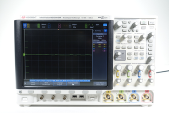
Browse Our Refurbished Oscilloscope Selection


Types of Timing Errors
Accurate measurements hinge on a precise understanding of the common types of timing errors that can affect an oscilloscope's performance.
Below, we delve into the nuances of jitter, skew, and trigger errors.
Jitter
Jitter manifests as random, small deviations in the timing of a digital system. This variance introduces uncertainty, affecting the stability and reliability of signal readings. Jitter can originate from multiple sources:
- Clock instability: Oscillators that generate the clock signal may have inherent instability, which then propagates through the system.
- External noise: Environmental factors like electromagnetic interference can introduce jitter.
- Circuit components: Inadequate decoupling or poor component quality can also introduce timing deviations.
To combat jitter, engineers commonly use jitter reduction techniques such as phase-locked loops (PLLs) and jitter buffers. Analyzing jitter usually involves statistical methods, focusing on the root mean square (RMS) or peak-to-peak values.
Skew
Skew is the timing misalignment that occurs when similar or related signals don't align as expected over time.
Skew generally affects parallel data systems and multi-channel measurements. The primary factors contributing to skew include:
- Path differences: Signals taking different physical paths can arrive at the oscilloscope inputs at slightly different times.
- Component discrepancies: Variability in component tolerances can create phase shifts in the signals.
- Inherent system lags: Propagation delays within the circuit or within the oscilloscope itself can result in skew.
Engineers can compensate for skew by applying correction factors during data analysis or by physically adjusting the system setup to minimize path differences.
Trigger Errors
Trigger errors occur when the oscilloscope starts capturing data at an incorrect point in time. This misalignment severely impacts the validity of your measurements and arises from several factors:
- Noise interference: Background noise can mislead the trigger mechanism, causing it to activate at the wrong time.
- Incorrect trigger settings: If the trigger level or type is not set correctly, the oscilloscope may either miss the event or trigger too early or too late.
- Signal abnormalities: Anomalies like spikes or drops in the signal can falsely trigger the capture mechanism.
To minimize trigger errors, choose the most appropriate triggering mechanism and ensure that your oscilloscope has a high signal-to-noise ratio. Fine-tuning the trigger settings for each specific measurement task can also improve accuracy.
By gaining a nuanced understanding of these timing errors, you can take effective measures to mitigate their impact and enhance the reliability of your oscilloscope measurements.
Parameters Affecting Timing
Mastering oscilloscope timing means understanding the key parameters that significantly influence it.
Let's dive into greater detail about sample rate, triggering mechanism, and bandwidth, exploring how each contributes to the oscilloscope's timing performance.
Sample Rate
Sample rate, usually measured in samples per second (S/s), determines how often the oscilloscope collects data points from the incoming signal.
A higher sample rate equates to finer time resolution, allowing for more detailed analysis of fast-changing signals. But there are some considerations to bear in mind:
- Aliasing: Under-sampling may lead to aliasing, a phenomenon where higher frequencies appear as lower frequencies, causing distorted measurements.
- Memory depth: A high sample rate may require substantial memory depth to store the captured data.
- Processing overhead: High sampling rates can demand more from the oscilloscope’s processing unit, potentially slowing down other functionalities.
Balancing the sample rate for your specific needs is crucial. The Nyquist-Shannon sampling theorem suggests that the sampling frequency should be at least twice the maximum frequency contained in the signal to adequately represent it.
Triggering Mechanism
The triggering mechanism serves as the oscilloscope's starting gun, signaling when to begin data capture.
Various triggering options offer flexibility but also require careful selection to ensure accurate timing. Here are some common types:
- Edge triggering: The most basic form, it starts capturing when the signal crosses a set voltage level. It works well for repetitive waveforms.
- Pulse-width triggering: This captures data based on the width of the pulse. It's useful for digital signals where the pulse duration is crucial.
- Video triggering: Designed for video signals, this type syncs to specific lines or fields in a video frame.
Selecting the right triggering mechanism can make a world of difference in measurement accuracy. In some cases, complex triggering options like sequence or logic triggering might be necessary to isolate specific events.
Bandwidth
Bandwidth defines the range of frequencies an oscilloscope can accurately measure. Typically expressed in Hertz (Hz), higher bandwidth allows for the precise capture of faster, higher-frequency signals. Key points to consider include:
- Frequency components: Signals are often composed of multiple frequency components. Insufficient bandwidth can eliminate higher frequencies, leading to an inaccurate representation of the signal.
- Rise time: Higher bandwidth allows the oscilloscope to capture faster rising edges, which is essential in digital systems.
- Attenuation: A limitation of bandwidth can result in attenuation, where the oscilloscope diminishes the amplitude of higher-frequency components.
The general rule of thumb is to choose an oscilloscope with a bandwidth at least five times higher than the maximum frequency of the signal you intend to measure.
Best Practices for Optimal Timing
Achieving optimal timing in your oscilloscope measurements necessitates a multi-faceted approach that goes beyond calibration.
This section elaborates on key best practices that contribute to optimal timing, including calibration, probe matching, and software configuration.
Calibration
Regular calibration is non-negotiable for ensuring that the internal clocks and scaling factors of your oscilloscope remain accurate. Calibration should be part of your maintenance schedule and involves:
- Internal diagnostics: Start with the internal diagnostics available on most modern oscilloscopes. This feature automatically checks various system components like clock stability and signal path integrity.
- Signal checks with a reference source: Use a calibrated signal generator to verify the oscilloscope's timing. Connect the oscilloscope to the signal generator, capture the output, and compare it to the known parameters.
- Adjustments as necessary: If discrepancies arise, make the necessary adjustments. Whether it's fine-tuning the internal clock or correcting gain settings, recalibration ensures your oscilloscope remains accurate for future measurements.
Probe Matching
Using the right probe is essential for avoiding skew and signal degradation. Keep the following points in mind:
- Impedance matching: Ensure that the probe's impedance matches the oscilloscope's input impedance. Mismatch can lead to signal reflection and errors.
- Bandwidth compatibility: The probe's bandwidth should also be compatible with the oscilloscope. A probe with insufficient bandwidth can filter out high-frequency components, leading to an incomplete signal representation.
By diligently selecting and using matched probes, you eliminate a significant source of timing errors.
Software Configuration
Modern oscilloscopes come bundled with sophisticated software that can significantly aid in optimizing timing. Here are some capabilities to look for:
- Automated Timing Adjustments
Advanced software can automate many aspects of timing adjustment, like correcting for skew or compensating for known sources of jitter. These features can save you considerable time during setup.
- Signal Processing Capabilities
Look for software that includes advanced signal processing algorithms. Features like Fourier Transform and filtering can help in analyzing the timing characteristics of your signals more accurately.
- Data Visualization Tools
Good visualization tools can make it easier to spot timing errors. Whether it's through waterfall plots, histograms, or 3D views, advanced visualization tools make data analysis more intuitive.
Buy Refurbished Oscilloscopes On Sale
Key Best Practices for Optimal Oscilloscope Timing
| Best Practice | Importance | Optimization Tips |
| Calibration | Accuracy of internal clocks | Conduct regularly |
| Probe Matching | Minimizes skew & errors | Match impedance & bandwidth |
| Software Configuration | Streamlines timing | Use automated & visualization tools |
Conclusion
Timing is the linchpin of accurate and reliable measurements in oscilloscopes. From calibration to probe matching and software configuration, a comprehensive approach ensures that you can trust the data you collect.
Whether you're capturing transient events or analyzing complex waveforms, the right practices can significantly boost the integrity of your results.
If you're looking to optimize your lab setup, consider investing in premium used equipment from Keysight.
The Keysight Used Equipment Store offers a wide range of rigorously tested and certified products, including oscilloscopes, spectrum analyzers, waveform generators, and multimeters.
Take the guesswork out of your measurements—choose Keysight for reliability and precision.
Whenever You’re Ready, Here Are 5 Ways We Can Help You
- Browse our Premium Used Oscilloscopes.
- Call tech support US: +1 800 829-4444
Press #, then 2. Hours: 7 am – 5 pm MT, Mon– Fri - Talk to our sales support team by clicking the icon (bottom right corner) on every offer page
- Create an account to get price alerts and access to exclusive waitlists.
- Talk to your account manager about your specific needs.