- Introduction
- What Is Phase Shift?
- Factors Influencing Phase Shift
- Frequency
- Components
- Signal Path
- Importance of Phase Shift: Why It Matters
- Signal Processing
- Control Systems
- Telecommunications
- Audio Engineering
- Measuring Phase Shift with an Oscilloscope: Hardware Essentials
- A Dual-Channel Oscilloscope
- Probes
- Signal Generator or Source Signals
- Step-by-Step Procedure: Detailed Guidelines for Measuring Phase Shift
- Step 1: Connect the Probes
- Step 2: Calibrate the Oscilloscope
- Step 3: Set Up Signals
- Step 4: Sync the Waveforms
- Step 5: Measure the Phase
- Step 6: Record Data
- Applications of Phase Shift in Various Fields
- Conclusion
- Whenever You’re Ready, Here Are 5 Ways We Can Help You
Did you know that the concept of phase shift plays an indispensable role in electrical and electronic measurements?
Phase shift can profoundly impact the behavior of signals, systems, and the results you get from an oscilloscope.
This article dives into the intricate details of what phase shift is, why it matters, and how to measure it using an oscilloscope.
What Is Phase Shift?
Phase shift refers to the angular difference between two sinusoidal waveforms at the same frequency.
We usually express it in degrees or radians, and it quantifies the time relationship between these signals. In essence, phase shift reveals how much one wave leads or lags behind another.
Mathematically, we can represent a sinusoidal signal \(x(t)\) as:
\(x(t)=Asin(2πft+ϕ)\)
Where:
- \(A\) is the amplitude
- \(f\) is the frequency
- \(t\) is the time
- \(ϕ\) is the phase
The phase shift \(Δϕ\) between two signals \(x _1\) (\(t\)) and \(x_2\) (\(t\)) is:
\(Δϕ = ϕ_1 − ϕ_2\)
| Key Takeaway |
|---|
| Understanding and accurately measuring phase shift is crucial for optimizing system performance across various engineering fields, from signal processing to control systems. Utilizing the right tools and methods ensures reliable measurements, enabling more effective design, troubleshooting, and optimization. |
Discover Keysight's Range of Certified Refurbished Oscilloscopes


Factors Influencing Phase Shift
Understanding what influences phase shift can provide a critical edge in applications ranging from telecommunications to control systems.
Let's delve into the three primary factors that affect phase shift: frequency, components, and signal path.
Frequency
The frequency of a signal directly correlates with its phase shift. At higher frequencies, reactive components like capacitors and inductors exhibit increasingly complex impedance behaviors.
This change in impedance impacts the phase relationships between voltage and current in the circuit. Here are some insights:
- Capacitors: At higher frequencies, capacitors offer less reactance, leading to a reduced lag between current and voltage, altering the phase shift.
- Inductors: Inductors display increased reactance at higher frequencies, which can increase the phase shift between voltage and current.
Components
Individual components like resistors, capacitors, and inductors play a significant role in determining the phase shift in electrical circuits. Each component type introduces its unique form of phase shift:
- Resistors: Generally, resistors do not introduce phase shift, as they are non-reactive elements. However, in combination with reactive elements, they can affect the overall phase conditions.
- Capacitors: Capacitors create a phase shift where the current leads the voltage by 90 degrees in a purely capacitive circuit.
- Inductors: In a purely inductive circuit, the voltage leads the current by 90 degrees, contributing to a different kind of phase shift.
Signal Path
While it may seem negligible, the signal path can significantly influence the phase shift. Several aspects of the signal path to consider are:
- Cable length: Longer cables can introduce a noticeable delay, translating into a phase shift between the transmitted and received signals.
- Cable type: Different materials and constructions (e.g., coaxial vs. twisted pair) can have distinct propagation delays, affecting the phase shift.
- Connectors and adapters: These can introduce additional impedance mismatches, subtly changing the phase relationship between signals.
By paying close attention to these factors, you can take greater control over the phase characteristics of your systems, ensuring accurate measurements and optimized performance.
Importance of Phase Shift: Why It Matters
The concept of phase shift permeates numerous fields, from telecommunications to audio engineering.
Understanding its importance can offer insights into system performance, optimization, and problem-solving.
Here, we expand on four key areas where phase shift plays a critical role.
Signal Processing
In signal processing, phase information is not just an added layer of data—it is a crucial part of the signal itself. Accurate phase measurements enable:
- Filter design: In high-pass, low-pass, and band-pass filters, phase characteristics dictate how effectively the filter separates frequency components.
- Modulation schemes: In techniques such as Quadrature Amplitude Modulation (QAM), the phase carries crucial information, affecting the integrity and efficiency of data transmission.
Control Systems
In control systems, particularly in feedback loops like PID controllers, the phase relationship between input and output signals can make or break system stability.
A system with incorrect phase data could oscillate uncontrollably, causing:
- Operational failures: Incorrect phase information can lead to shutdowns or erratic behavior.
- Inefficient performance: Systems may operate, but not optimally, wasting resources and time.
Telecommunications
Phase shift plays an indispensable role in modern telecommunication technologies. In Phase Shift Keying (PSK), for example, the phase of the carrier signal changes to represent the data. This method offers:
- Data integrity: PSK is less susceptible to noise, ensuring better data transmission.
- Bandwidth efficiency: PSK schemes, like QPSK or 8-PSK, make better use of available bandwidth, allowing for higher data rates.
Audio Engineering
In the realm of audio engineering, phase relationships between channels and frequencies deeply impact the sound experience. Phase issues can cause:
- Sound cancellation: Incorrect phase alignment may lead to some frequencies canceling each other out.
- Localization errors: Incorrect phase relationships can distort the perception of where a sound is coming from, disrupting the audio experience.
Recognizing the vital role that phase shift plays in these areas enables engineers and professionals to make informed decisions, troubleshoot effectively, and optimize systems for peak performance.
Measuring Phase Shift with an Oscilloscope: Hardware Essentials
When it comes to measuring phase shift, the tools you use are as crucial as the methodologies you employ.
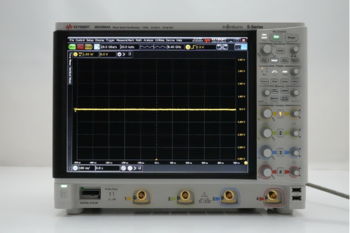
A Dual-Channel Oscilloscope
Oscilloscopes come in various forms, but a dual-channel oscilloscope is essential for measuring phase shift between two signals. Here's why:
- Simultaneous viewing: A dual-channel oscilloscope allows you to observe both signals side-by-side, simplifying phase comparisons.
- Advanced calculations: Modern oscilloscopes often come with built-in mathematical functions that can directly calculate the phase difference, saving you time and effort.
Probes
Your probes serve as the crucial link between the circuit or system under test and your oscilloscope. Therefore, selecting the right probe is critical.
Key considerations include:
- Bandwidth: Ensure that the probe's bandwidth matches or exceeds that of the oscilloscope and the signals you're measuring.
- Impedance matching: An impedance mismatch can introduce inaccuracies, including erroneous phase data.
- Probe calibration: Before measurements, calibrate the probes to ensure that they are not introducing any phase errors themselves.
Signal Generator or Source Signals
You'll need a stable signal source for your phase shift measurements. The source can either be the system you are testing or a standalone signal generator.
Here are the key aspects to consider:
- Stability: A stable signal source ensures that any phase shifts you measure are inherent to the system under test, not a result of fluctuations in the source.
- Frequency range: Make sure that the signal generator or source signals cover the frequency range relevant to your tests.
- Waveform quality: The signal should be as clean as possible to avoid complicating your phase measurements with noise or other distortions.
Proper hardware not only ensures accurate measurements but also streamlines the measurement process, making it more efficient and reliable.
By investing in the right tools and understanding their capabilities and limitations, you can elevate the precision and reliability of your phase shift assessments.
Step-by-Step Procedure: Detailed Guidelines for Measuring Phase Shift
Step 1: Connect the Probes
Begin by turning off the oscilloscope for safety precautions. Then inspect the probes for any signs of wear or damage on the tips and cables.
Once verified, insert the probes into the appropriate channels on the oscilloscope.
Finally, attach the probe tips to the circuit points where you plan to measure the signals.
Step 2: Calibrate the Oscilloscope
Turn on the oscilloscope and allow it some time to warm up if needed. Use the probe compensation output to calibrate the probes, ensuring they are accurately representing the signals.
If your oscilloscope comes with a self-calibration function, it’s a good idea to run it to ensure all internal settings are optimized for accurate measurement.
Step 3: Set Up Signals
First, choose your source for the signals. This can either be a signal generator or the system you are examining.
Once you have your source, feed the two signals into the channel 1 (CH1) and channel 2 (CH2) inputs on the oscilloscope. Make sure to adjust the vertical and horizontal scales appropriately.
You should aim to set the vertical scale (Volts/Div) and the horizontal scale (Time/Div) in such a way that the waveforms are clearly visible on the screen.
Step 4: Sync the Waveforms
Start by selecting which channel you want to use as the trigger source, which is often CH1.
Adjust the trigger level to a point where the oscilloscope can consistently capture the waveform. This will help in stabilizing the waveform on the display.
Confirm that both waveforms appear stable on the display and are not drifting or jumping around.
Step 5: Measure the Phase
First, enable the measurement cursors on your oscilloscope. Place one cursor on a reference point on the first waveform and the other on the corresponding point on the second waveform.
If your oscilloscope comes with a built-in phase measurement function, you can opt for that to automatically calculate the phase difference. Otherwise, you will need to note the time difference and calculate the phase shift using the formula.
Step 6: Record Data
Use the oscilloscope’s screenshot function to capture a picture of the waveforms if available. Also, manually note down all relevant settings, measurements, and calculations. This is crucial for future reference or further analysis.
If your oscilloscope supports data transfer, take this opportunity to send the data to a computer where you can analyze it in greater detail.
By meticulously following each of these steps, you can achieve accurate and reliable phase shift measurements, thereby enhancing your understanding and control of complex electronic systems.
Discover the Exceptional Value: Refurbished Oscilloscopes from Keysight
Applications of Phase Shift in Various Fields
| Field | Application | Importance of Phase Shift |
| Electrical Engineering | AC circuit analysis | Determines circuit impedance |
| Telecommunications | Signal encoding and decoding | Key to data integrity |
| Control Systems | PID controllers | Ensures system stability |
| Audio Engineering | Multi-channel sound systems | Affects sound localization |
| Medical Imaging | MRI | Essential for image reconstruction |
Conclusion
Understanding and accurately measuring phase shift is an integral part of electrical engineering and related fields.
Whether optimizing a control system, enhancing a telecommunications network, or fine-tuning an audio experience, the impact of phase shift is profound and wide-ranging.
By following a systematic approach and using precise tools, you can master this complex yet essential parameter.
If you're looking to elevate your testing capabilities, why settle for anything less than the best?
Visit Keysight Used Equipment Store to explore an extensive range of premium used oscilloscopes, signal analyzers, waveform generators, and multimeters.
Equip yourself with top-of-the-line, reliable instruments that bring precision to your work without breaking the bank.
Whenever You’re Ready, Here Are 5 Ways We Can Help You
- Browse our Premium Used Oscilloscopes.
- Call tech support US: +1 800 829-4444
Press #, then 2. Hours: 7 am – 5 pm MT, Mon– Fri - Talk to our sales support team by clicking the icon (bottom right corner) on every offer page
- Create an account to get price alerts and access to exclusive waitlists.
- Talk to your account manager about your specific needs.