- Introduction
- Understanding Delay in Electronics
- Types of Delay in Electronics
- Propagation Delay
- Transmission Delay
- Processing Delay
- Queuing Delay
- Key Factors Contributing to Delay in Electronic Circuits
- Circuit Complexity
- Material Properties
- Temperature
- Interference
- Additional Considerations
- Techniques for Measuring Delay in Electronics
- Step-by-Step Measurement Using Oscilloscopes
- Other Methods and Equipment
- Factors Affecting Measurement Accuracy
- Good Practices in Measuring Delay
- Delay Specifications
- Conclusion
- Whenever You’re Ready, Here Are 5 Ways We Can Help You
Have you ever pressed a button on a remote control and experienced a noticeable delay before the television responds?
This common frustration is a symptom of 'delay' in electronics, a critical factor that engineers and technicians strive to minimize during design and testing phases.
Understanding Delay in Electronics
Delay, often measured in milliseconds or microseconds, is the time interval between the input signal and the response from an electronic system.
In the world of electronics, this delay is not just an inconvenience; it can significantly impact the performance and reliability of systems ranging from simple household appliances to complex telecommunications networks.
| Key Takeaway |
|---|
| Delays in electronics, spanning from propagation to queuing, are critical factors that can significantly impact the performance of electronic systems, necessitating precise measurement and mitigation using advanced tools like oscilloscopes to ensure optimal system functionality. |
Types of Delay in Electronics
When you're working with electronic systems, understanding the nuances of different types of delay can be critical for troubleshooting and system optimization. Let's delve deeper into the common delays encountered in electronic systems.
Propagation Delay
Propagation delay is the time it takes for a signal to travel through a component or from the sending end to the receiving end of a circuit. This type of delay is inherent in all physical mediums through which the signal travels, including wires, fiber optic cables, and even wireless mediums.
Factors affecting propagation delay include:
- Length of the medium: A longer wire or PCB trace naturally results in a longer propagation delay.
- Signal speed: Depending on the medium, signals travel at different speeds. For example, electrical signals move close to the speed of light in a vacuum, but slower in copper wire.
- Dielectric material: The type of insulation surrounding the conducting material can also impact the speed at which the signal propagates.
Transmission Delay
Transmission delay, sometimes confused with propagation delay, refers specifically to the time it takes for all the bits of a message to leave the transmitter. This delay is a function of the message's length and the data rate of the transmission medium.
For example:
- In a network, transmission delay would be the time taken for a router to push out a packet.
- For a serial communication link, it's the time from when the transmission of a byte starts until the last bit is sent out of the wire.
Processing Delay
Processing delay is the time a device takes to handle an incoming signal and is affected by various factors:
- Device architecture: The design and complexity of the processor or logic gates can impact the speed of processing.
- Operational load: If a device is performing multiple tasks or handling several signals at once, this can introduce additional processing delay.
- Software efficiency: In devices where software plays a role in processing, the efficiency of the code can greatly affect the processing time.
Queuing Delay
Queuing delay occurs when a signal or data packet arrives at a point where it must wait before being processed due to congestion.
This is often seen in networking equipment such as routers and switches where data packets can arrive faster than the processing capability, causing a queue to form.
Characteristics of queuing delay include:
- Buffer size: The size of the queue buffer will determine how long data can be held before being dropped or timed out.
- Traffic load: Higher data traffic can increase queue lengths, leading to greater delays.
- Priority handling: Some systems use priority queues to manage delay, where certain signals are given precedence over others.
Understanding these delays is crucial for electronic and communication engineers, especially when designing systems that require real-time response or when troubleshooting issues that could be causing system lag.
Delays are often interdependent, and reducing one can sometimes increase another, so a balanced approach is necessary.
For example, reducing propagation delay by using shorter wires might increase queuing delay if the signals reach a congested point more quickly. Therefore, it’s imperative to consider the entire system when aiming to minimize delays.
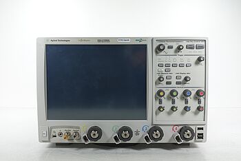
Discover Our Selection of Used Oscilloscopes


Key Factors Contributing to Delay in Electronic Circuits
Delays in electronic circuits can be the bane of an efficient system. To tackle them, it's vital to understand the underlying factors that contribute to these delays. Here’s a closer look at each one.
Circuit Complexity
The complexity of a circuit plays a significant role in the introduction of delays. The logic of the circuit, the number of components it contains, and how they are interconnected all contribute to the overall delay.
- Number of gates: In digital circuits, the more logic gates a signal must pass through, the greater the cumulative propagation delay.
- Interconnect lengths: Longer paths between components can increase both propagation and transmission delays.
- Switching activity: High-frequency switching can introduce dynamic delays, as different paths may have varying switch times.
Material Properties
The materials from which the components and the PCB (Printed Circuit Board) are made can greatly influence the delay.
- Conductivity: Materials with higher electrical conductivity, like silver or copper, have lower resistivity, leading to lower propagation delays.
- Permittivity and permeability: The dielectric constant and magnetic permeability of materials can affect how fast the signal propagates through the medium.
- Quality of the material: Impurities and variations in the material structure can cause inconsistencies in signal propagation, leading to variations in delay.
Temperature
Temperature can have a dual effect on electronic components and their delay characteristics.
- Resistance: As temperature increases, the resistance of conductive materials generally increases, which can slow down the electron flow and increase delay.
- Semiconductor behavior: Semiconductor devices, like transistors, can have their switching characteristics altered by temperature, which affects the processing delay.
Interference
Electromagnetic interference (EMI) is a significant factor that can induce unwanted delays in an electronic circuit.
- Signal integrity: External EMI can distort signal integrity, leading to errors that require retransmission or additional error correction processing.
- Crosstalk: In densely packed circuits, crosstalk between nearby wires or traces can introduce noise and delay due to the need for signal reprocessing or error handling.
- Shielding and grounding: Poor shielding and grounding can exacerbate interference issues, increasing delays and the potential for signal corruption.
Additional Considerations
While the factors mentioned above are among the most prominent, other considerations can also contribute to delay:
- Power supply stability: Fluctuations in the power supply can affect the performance of active components, leading to variable processing delays.
- Age and wear: Over time, components can degrade, altering their characteristics and potentially increasing delay.
- Software efficiency: For devices that rely on firmware or software, the efficiency of the code can greatly affect processing times.
Understanding these factors allows engineers to design more efficient circuits and troubleshoot delay-related problems more effectively.
By considering each element in the context of the entire system, it’s possible to optimize circuits for minimal delay, ensuring faster and more reliable electronic systems.
Techniques for Measuring Delay in Electronics
The process of measuring delay is crucial for engineers who are concerned with the optimization and functionality of electronic systems.
Oscilloscopes, among other tools, are indispensable in this process. Let's delve into the methodologies engineers employ to gauge delay with precision.
Step-by-Step Measurement Using Oscilloscopes
- Prepare the equipment: Engineers begin by setting up the oscilloscope, ensuring it is calibrated correctly for accurate measurements.
- Connect the device: They connect the oscilloscope's probes to the output of the device under test (DUT). One probe is used for the reference input signal, and another is connected to the point where the output signal can be observed.
- Signal application: A signal, often a pulse or a square wave, is then applied to the input of the DUT. This signal must be well-defined so that its leading edge can be used as a reference point.
- Observe the signals: The oscilloscope displays the input and output waveforms. The engineer observes the waveforms to ensure they are clear and that the trigger point is correctly set.
- Measure time difference: Using the oscilloscope's cursors, the engineer marks the leading edge of the input signal and the leading edge of the output signal. The oscilloscope then calculates the time difference between these two points, which is the delay.
- Automated functions: Modern digital oscilloscopes often have automated functions that can measure the delay between two signals with a push of a button, significantly simplifying the process.
Other Methods and Equipment
While oscilloscopes are commonly used for measuring delays, there are additional tools and methods that engineers might employ:
- Time-Domain Reflectometers (TDR): These are used for measuring the propagation delay of cables and identifying faults.
- Network Analyzers: For high-frequency RF circuits, network analyzers can be utilized to measure delays accurately.
- Logic Analyzers: In digital circuits, logic analyzers can be used to measure the time between various digital events with high precision.
Factors Affecting Measurement Accuracy
When measuring delay, several factors can affect the accuracy of the results:
- Bandwidth of the oscilloscope: An oscilloscope with higher bandwidth can more accurately capture the true shape of the signals, leading to more precise delay measurements.
- Probe quality: The quality and type of probe used (passive or active) can influence the fidelity of the signal being measured.
- Signal integrity: If the signal is noisy or has a poor rise time, it can make it difficult to identify the exact points for measurement.
- Sampling rate: The oscilloscope’s sampling rate must be high enough to accurately reconstruct the signals.
Good Practices in Measuring Delay
Engineers follow certain good practices to ensure accurate delay measurement:
- Signal conditioning: Using filters or signal conditioners to clean up the signal before it is measured can improve accuracy.
- Reference points: Clearly define reference points for measurement. For digital signals, this is typically the point where the signal crosses a specific voltage threshold.
- Environment control: Minimizing environmental factors such as EMI or vibrations that can affect measurements.
- Repeatability: Performing multiple measurements and averaging the results can help account for any variations or transient conditions.
By adhering to these meticulous procedures, engineers can reliably measure and analyze delays, enabling them to fine-tune electronic systems for optimal performance.
Delay Specifications
| Device Type | Propagation Delay (ns) | Processing Delay (µs) | Total Delay (ms) |
|---|---|---|---|
| Digital Logic Gate | 0.5 – 10 | N/A | < 1 |
| Microprocessor | 10 – 30 | 100 – 1000 | 1 – 10 |
| Hard Drive | 500 – 2000 | 5000 – 15000 | 5 – 20 |
| Network Router | 5 – 40 | 1000 – 3000 | 1 – 5 |
Note: These values are approximate and can vary based on the specific model and manufacturer.
Explore Keysight’s Range of Oscilloscopes Today
Conclusion
In the realm of electronics, delay is an omnipresent parameter that professionals must navigate with precision and understanding. It is more than a mere inconvenience—it can dictate the performance and reliability of complex electronic systems, from simple circuits to vast communication networks.
Engineers employ sophisticated tools and methodologies, like oscilloscopes and network analyzers, to measure and mitigate these delays, ensuring their designs meet the stringent demands of modern technology.
However, achieving the highest level of precision doesn’t always require the steepest investment. Keysight’s Used Equipment Store offers an excellent array of premium used testing equipment.
Here, you can find top-of-the-line oscilloscopes, spectrum analyzers, waveform generators, and multimeters.—each rigorously inspected and refurbished to meet original factory specifications.
Enhance your testing capabilities while optimizing your budget, ensuring you’re equipped to measure, analyze, and tackle delays in any electronic system.
Whenever You’re Ready, Here Are 5 Ways We Can Help You
- Browse our Premium Used Oscilloscopes.
- Call tech support US: +1 800 829-4444
Press #, then 2. Hours: 7 am – 5 pm MT, Mon– Fri - Talk to our sales support team by clicking the icon (bottom right corner) on every offer page
- Create an account to get price alerts and access to exclusive waitlists.
- Talk to your account manager about your specific needs.