- Introduction
- What is Coupling?
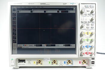
- Discover Our Selection of Used Oscilloscopes
- Types of Coupling
- DC Coupling: The Universal Connector
- AC Coupling: The High-Pass Gatekeeper
- Ground Coupling: The Diagnostic Tool
- Selecting the Right Coupling Mode: A Guided Approach
- Assess the Type of Signal
- Consider the Frequency Range
- Evaluate the Importance of DC Information
- Decision Flow for Coupling Mode Selection
- Common Pitfalls and Solutions
- Incorrect Coupling Choice
- Ignoring Noise Levels
- Misinterpreting Low-Frequency Signals
- Coupling Modes in Oscilloscopes: A Quick Reference Guide
- Conclusion
- Whenever You’re Ready, Here Are 5 Ways We Can Help You
How often do you pause to consider the coupling settings on your oscilloscope? Despite being a small button or menu option on the screen, the coupling feature holds the key to unlocking accurate and insightful measurements.
For electrical engineers and professionals using oscilloscopes, a nuanced understanding of coupling can dramatically elevate the quality of signal analysis and troubleshooting.
This comprehensive guide dives deep into what coupling in oscilloscopes is, its types, applications, and how to avoid common pitfalls.
What is Coupling?
Coupling in oscilloscopes refers to the method used to connect the input signal to the oscilloscope's internal circuitry.
This seemingly simple connection profoundly influences how the oscilloscope displays the signal, affecting various parameters like amplitude, frequency components, and even noise levels.
The coupling sets the conditions for your signal path, determining which parts of the signal—DC, AC, or a mixture of both—are analyzed and displayed.
| Key Takeaway |
|---|
Choosing the right coupling mode in an oscilloscope is crucial for accurate and insightful signal analysis. Your selection serves as a filter that either reveals or masks essential components of the signal, impacting the quality and reliability of your measurements. |
Discover Our Selection of Used Oscilloscopes


Types of Coupling
DC Coupling: The Universal Connector
When you opt for DC coupling, you're choosing the most straightforward connection between your input signal and the oscilloscope's circuitry.
In this mode, no alterations or filtering occurs to the signal. You see the raw, unfiltered data, capturing both its AC and DC components.
Intricacies of DC Coupling
- Frequency response: DC coupling offers a flat frequency response, meaning it accurately portrays signals from zero frequency (DC) up to the bandwidth limit of the oscilloscope.
- Direct measurement: Because it allows both AC and DC components to pass, you can directly measure static voltage levels in addition to changing signals.
DC coupling suits a range of applications, including:
- Digital logic design
- Power supply testing
- Situations where you need to examine both DC and AC behavior in a circuit
AC Coupling: The High-Pass Gatekeeper
AC coupling stands out for its ability to filter out the DC component of a signal. A capacitor is placed in series with the input, acting as a high-pass filter that blocks DC and allows only AC signals to pass through.
Intricacies of AC Coupling
- Cutoff frequency: The capacitor introduces a cutoff frequency below which signals get attenuated. It’s essential to know this cutoff frequency to accurately interpret low-frequency components.
- Dynamic range: With the DC component removed, the oscilloscope can focus on the AC portion of the signal, sometimes enabling a higher resolution for AC amplitude measurements.
AC coupling is beneficial for:
- Analyzing modulated signals
- Examining AC signals superimposed on DC offsets
- Measuring ripple on a DC power supply
Ground Coupling: The Diagnostic Tool
Ground coupling seems like a non-intuitive option because it essentially disconnects your signal input.
Your probe tip gets directly connected to the ground, rendering the screen to display a flat line.
While you won't use ground coupling to measure active signals, it serves diagnostic and calibration purposes.
Intricacies of Ground Coupling
- Noise assessment: With ground coupling, you isolate the oscilloscope's internal noise, allowing you to evaluate its level without any external signals.
- Ground reference: It sets a zero-voltage level on your oscilloscope screen, providing a reference point for subsequent measurements.
Ground coupling is particularly useful for:
- Calibration tasks
- Establishing a noise floor
- Preparing the oscilloscope for differential measurements
By diving into the intricacies of these coupling types, you can make more informed decisions about which to use, enhancing the quality and accuracy of your signal measurements.
Selecting the Right Coupling Mode: A Guided Approach
The coupling mode you choose on your oscilloscope significantly influences the quality and accuracy of your measurements.
Because each coupling mode has its strengths and limitations, it's essential to align your choice with the specific requirements of the application you're working on.
Here's an in-depth look at the factors you should consider when selecting the right coupling mode.
Assess the Type of Signal
The first step in selecting the appropriate coupling mode involves understanding the nature of the signal you're dealing with.
- Purely AC signals: If you're dealing with signals that have no DC component or where the DC component is irrelevant, AC coupling can simplify your measurements by focusing solely on the AC components.
- Purely DC signals or mixed signals: When the signal has important DC components that you can't ignore, DC coupling becomes the obvious choice. This mode also works well for mixed signals that have both AC and DC characteristics.
Consider the Frequency Range
Different coupling modes interact differently with various frequency ranges, making the frequency of the signal components a critical consideration.
- Low-frequency components: If your signal has significant low-frequency or DC components, DC coupling is generally more suitable. AC coupling would cut off these frequencies, causing a loss of information.
- High-frequency components: For high-frequency signals or if you're interested in seeing higher frequency fluctuations around a DC level, AC coupling is often more appropriate.
Evaluate the Importance of DC Information
The need to measure or preserve DC information often dictates the choice of coupling mode.
- DC level critical: In applications like biasing circuits, sensor outputs, or battery-operated devices, DC levels are often as crucial as any AC variation. Here, DC coupling becomes essential.
- DC level not critical: In instances where the DC level either doesn't carry meaningful information or could confuse the readings (like ripple measurements on a DC power supply), AC coupling might serve you better.
Decision Flow for Coupling Mode Selection
- Identify the signal type: AC, DC, or mixed.
- Analyze the frequency components: High, low, or broad spectrum.
- Determine the need for DC information: Critical or not.
Common Pitfalls and Solutions
Even seasoned electrical engineers can encounter challenges related to oscilloscope coupling. Below, we examine some of the most common pitfalls and offer solutions to navigate these issues effectively.
Incorrect Coupling Choice
Symptom: Signal Distortion or Shift
Choosing the wrong coupling mode can result in a distorted or shifted signal, making your measurements unreliable.
Solution: Reevaluate and Switch
- Immediate action: Switch to another coupling mode and compare the signals. For instance, if you initially chose AC coupling, try switching to DC coupling to see if the DC component was causing the distortion.
- Long-term strategy: Familiarize yourself with the characteristics of different coupling modes. Doing so allows you to predict how each mode will interact with various types of signals, reducing the likelihood of making an incorrect choice.
Ignoring Noise Levels
Symptom: High Noise on Signal
If your measurements have high noise levels superimposed on the actual signal, your data will be inaccurate, and troubleshooting will become difficult.
Solution: Verify and Establish Noise Baseline
- Immediate action: Use ground coupling to detach the input signal and view only the internal noise. This process helps you establish a noise baseline.
- Long-term strategy: Consider investing in probes and cables that are specifically designed to minimize noise. Also, be vigilant about ground loops and other sources of external noise that may interfere with measurements.
Misinterpreting Low-Frequency Signals
Symptom: Missing or Truncated Low Frequencies
When low-frequency components appear truncated or entirely missing, it's often because the AC coupling mode filters them out.
Solution: Capture the Full Spectrum with DC Coupling
- Immediate action: Switch to DC coupling to allow low-frequency and DC components to pass through. Reexamine the signal to check if the previously missing components now appear.
- Long-term strategy: Before initiating measurements, make a mental checklist to ensure the chosen coupling mode aligns with the frequency components of interest, particularly if they are on the lower end of the spectrum.
By being aware of these common pitfalls and knowing how to circumvent them, you'll be better equipped to make accurate and reliable measurements.
The key is to understand not just how to operate the oscilloscope, but also how your choices regarding coupling modes impact the quality of your data.
Coupling Modes in Oscilloscopes: A Quick Reference Guide
| Coupling Type | Key Attributes | Ideal Use-Cases | Common Pitfalls |
|---|---|---|---|
| DC Coupling | Flat frequency response, direct measurement | Digital logic design, power supply testing | Incorrect choice leading to distorted signals |
| AC Coupling | High-pass filter, cutoff frequency | Modulated signals, ripple measurement | Ignoring noise levels, missing low frequencies |
| Ground Coupling | Diagnostic, noise assessment | Calibration, noise baseline | Not useful for active signal measurements |
Empower Your Projects With a Used Keysight Oscilloscope
Conclusion
Coupling in oscilloscopes isn't just a button to press or a menu option to select; it's a strategic choice that impacts the quality, reliability, and relevance of your measurements.
Whether you're dealing with digital logic designs, analyzing modulated signals, or calibrating your equipment, understanding the different types of coupling and their ideal applications can significantly enhance your diagnostic and analytical capabilities.
If this comprehensive guide on coupling has you eager to put your knowledge to the test, consider upgrading your equipment to ensure the best performance.
Visit Keysight Used Equipment Store for a range of premium used oscilloscopes, spectrum analyzers, waveform generators, and multimeters. Secure high-quality gear without breaking the bank and take your signal analysis to the next level.
Whenever You’re Ready, Here Are 5 Ways We Can Help You
- Browse our Premium Used Oscilloscopes.
- Call tech support US: +1 800 829-4444
Press #, then 2. Hours: 7 am – 5 pm MT, Mon– Fri - Talk to our sales support team by clicking the icon (bottom right corner) on every offer page
- Create an account to get price alerts and access to exclusive waitlists.
- Talk to your account manager about your specific needs.