- Introduction
- What is a Band Pass Filter?
- Types of Band Pass Filters
- Key Parameters of Band Pass Filters
- Designing Band Pass Filters
- Common Issues and Troubleshooting in Band Pass Filters
- Filter Instability
- High Insertion Loss
- Unexpected Behavior Near Cut-off Frequencies
- Conclusion
- Whenever You’re Ready, Here Are 5 Ways We Can Help You
The world around us is constantly humming, buzzing, and chattering with frequencies. What if we could handpick frequencies from the vast spectrum that surrounds us and 'tune in' to just a narrow slice of this frequency spectrum at a time? This scenario is the very foundation of a technology we use every day: Band Pass Filters (BPFs).
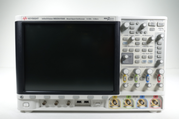
Buy Oscilloscopes at a Great Discount


What is a Band Pass Filter?
A Band Pass Filter (BPF) is an essential electronic component that allows frequencies within a specific range to pass through while rejecting frequencies outside this range. The frequencies that a BPF allows are situated between a lower cut-off frequency (fL) and an upper cut-off frequency (fH), often referred to as the 'passband'. Frequencies outside this range constitute the 'stopband.'
Types of Band Pass Filters
There are several types of BPFs, primarily divided into two categories:
1. Active Band Pass Filters: Active BPFs use active components like op-amps, along with capacitors and resistors, to form the filter. These filters amplify the input signal in addition to filtering, but they require an external power source.
2. Passive Band Pass Filters: Passive BPFs use only passive components like resistors, capacitors, and inductors. These filters don't amplify the signal and don't require external power. They're often used in audio frequency applications due to their simplicity and effectiveness.
| Key Takeaway |
|---|
| Band pass filters, integral components in numerous electronics and communication systems, allow a specific range of frequencies to pass while rejecting the rest. Engineers can optimize filters for various applications, such as audio processing and biomedical technologies, by understanding their design parameters, types, applications, and the detailed testing process with equipment like oscilloscopes. |
Key Parameters of Band Pass Filters
Understanding a BPF's key parameters is crucial for any electrical engineer. These parameters define the filter's behavior and are as follows:
- Center Frequency (fC): This is the midpoint frequency between fL and fH.
- Bandwidth (BW): This is the range of frequencies that the BPF allows. It's calculated by subtracting fL from fH.
- Quality Factor (Q): This is the ratio of the center frequency to the bandwidth. High Q values denote a narrower passband.
The following table summarizes these parameters:
| Parameter | Symbol | Formula | Description |
| Lower Cut-off Frequency | fL | - | The lower bound of the passband |
| Upper Cut-off Frequency | fH | - | The upper bound of the passband |
| Center Frequency | fC | (fH + fL) / 2 | The midpoint frequency in the passband |
| Bandwidth | BW | fH – fL | The total range of frequencies in the passband |
| Quality Factor | Q | fC / BW | Denotes the 'sharpness' of the passband |
Designing Band Pass Filters
The design of BPFs is often a trade-off between selectivity (how sharply the filter cuts off outside the passband) and insertion loss (how much the filter attenuates the signal within the passband). While high selectivity is desirable, it often leads to higher insertion loss, so engineers must balance these two factors.
Basic Steps to Design a BPF
- Identify the desired passband (fL and fH).
- Choose between an active or passive filter based on the application.
- Select the appropriate order for the filter. Higher-order filters provide better selectivity but are more complex.
Applications of Band Pass Filters
From telecommunications to audio processing, BPFs have a multitude of applications. Some notable ones include:
- Radio and TV Broadcasting: BPFs are used in receivers to isolate the desired channel frequency.
- Audio Processing: BPFs allow a specific range of frequencies to pass, enhancing certain aspects of the audio.
- Biomedical Applications: BPFs are used in electrocardiograms (ECGs) and other medical equipment to filter out noise.
Testing Band Pass Filters
Effective testing and analysis of band pass filters (BPFs) not only ensures their performance but also aids in understanding their characteristics and potential limitations. Testing involves understanding the frequency response of the filter and seeing how it reacts to various input signals. Here is a more detailed process of testing BPFs:
- Setup and Calibration: Begin by setting up the test environment. This step typically involves using a function generator, oscilloscope, and a digital multimeter (DMM). Calibration is critical to ensure the testing equipment is accurate. Ensure that the function generator is set up to produce a sinusoidal waveform with a frequency within the expected passband of the BPF.
- Connecting the BPF: After calibration, connect the BPF to the function generator's output and the oscilloscope's input. The function generator provides the test signals, while the oscilloscope allows you to observe the output from the filter.
- Initial Test Signal: Set the function generator to produce a frequency that is well within the passband of the BPF. This is the frequency where the filter should have the least attenuation.
- Verification of Passband: Verify the output of the filter using the oscilloscope. The output should show minimal attenuation. If the output shows significant attenuation, there could be a problem with the BPF, or it might not be designed as intended.
- Sweep Test: Once the passband is verified, perform a frequency sweep. Slowly increase the frequency of the input signal from the lower cutoff frequency (fL) to the upper cutoff frequency (fH). Observe the amplitude of the output signal on the oscilloscope.
- Plot the Frequency Response: As you sweep the input frequencies, record the amplitude of the output signals. Using these data points, plot the frequency response of the BPF. The plot should show a clear passband region with the signal amplitude dropping off significantly beyond the cut-off frequencies.
- Analyze the Results: Finally, analyze the data and the frequency response plot to evaluate the filter's performance. Check the bandwidth, center frequency, and the roll-off rates at the cut-off frequencies. If the filter's performance does not meet the design specifications, adjustments may be needed.
Common Issues and Troubleshooting in Band Pass Filters
Just like any other electronic components, band pass filters can also encounter issues in their operation. Understanding these potential problems and knowing how to troubleshoot them are crucial for any engineer dealing with these filters.
Filter Instability
One common issue is filter instability, which might cause the output to oscillate wildly or the filter to self-oscillate. This often occurs in active BPFs due to improper gain or phase margins in the design.
Troubleshooting: Check the design of the filter, particularly if it is an active filter. Look for any potential feedback loops that might be causing instability. If the design appears to be fine, examine the filter for faulty components, which might also cause unstable operation.
High Insertion Loss
Another problem could be high insertion loss, which is the loss of signal power resulting from the insertion of a device in a transmission line. If a BPF has high insertion loss, it might attenuate the signals within the passband more than expected.
Troubleshooting: To tackle high insertion loss, first check the specifications of your BPF. If it's within the spec, then it might be a design issue. Look into your filter design and see if you can reduce the insertion loss, perhaps by using components with lower resistance or by tweaking the design to have a higher Q factor.
Unexpected Behavior Near Cut-off Frequencies
At times, a BPF might show unexpected behavior near the cut-off frequencies, either passing frequencies it should block or blocking frequencies it should pass.
Troubleshooting: Check the filter's design and see if the cut-off frequencies have been correctly calculated. Also, inspect the components and make sure they are working as expected. Keep in mind that real-world components often don't behave exactly as their ideal counterparts due to factors like parasitic capacitance or inductance, which might impact the filter's performance.
Conclusion
Band pass filters, with their innate ability to tune into specific frequencies, are indispensable components in a wide range of applications. As an engineer, understanding the intricacies of BPFs, from their design parameters and types to their applications, common issues, and testing procedures, can greatly enhance your projects' effectiveness.
With patience, practice, and the right tools at your disposal, designing and testing BPFs can become second nature. In this constantly evolving field, staying abreast of common issues, troubleshooting methods, and recent trends can give you a competitive edge.
And when it comes to the right tools, Keysight's Used Equipment Store can be your ally. With an extensive range of high-quality, pre-owned testing equipment, you can ensure your BPFs and other components are working as expected without breaking your budget. Experience the reliability and performance of Keysight's solutions and take your engineering projects to the next level.
Take a step towards mastering the world of frequencies today by visiting Keysight's Used Equipment Store.
Browse Oscilloscopes at a Great Discount
Whenever You’re Ready, Here Are 5 Ways We Can Help You
- Browse our Premium Used Oscilloscopes.
- Call tech support US: +1 800 829-4444
Press #, then 2. Hours: 7 am – 5 pm MT, Mon– Fri - Talk to our sales support team by clicking the icon (bottom right corner) on every offer page
- Create an account to get price alerts and access to exclusive waitlists.
- Talk to your account manager about your specific needs.