- Introduction
- What is a Multimeter?
- Upgrade Your Toolkit with Keysight’s Fast Delivery on Refurbished Multimeters
- Basic Features On Your Multimeter
- Multimeter Display
- Dial
- Ports
- How to Select the Correct Function and Range
- Auto-Range vs. Manual Range Selection
- How to Read a Multimeter
- Measuring Voltage
- Measuring Current
- Measuring Resistance
- Measuring Continuity
- Diode Testing
- Advanced Functions
- Summary Table
- Understanding and Interpreting Results
- Troubleshooting Common Issues
- Calibration and Maintenance
- Discover Precision with Keysight's Trusted Premium Used Equipment
- Conclusion: Empower Your Electrical Diagnostics Today
- Whenever You’re Ready, Here Are 5 Ways We Can Help You
"Can I really rely on this multimeter to provide accurate readings and not let me down when things get tricky?"
You need a multimeter that stands up to the test, especially when you're deep into diagnosing a complex electrical issue or when you're trying to pinpoint a sensitive electrical issue.
This guide will equip you with the know-how to help you master its use. Whether it's troubleshooting a stubborn electrical problem, verifying the performance of a circuit, or routine checks, this guide will cover all the essential techniques needed to ensure your success.
What is a Multimeter?
A multimeter is an essential tool for anyone working with electricity. It's a handheld device that combines several measurement functions into one unit, primarily used to measure voltage, current, and resistance.
These versatile instruments are indispensable in the field of electrical engineering, auto repair, and many DIY projects involving electronics.
Multimeters have evolved significantly over the years, transitioning from analog to digital models. Let's break down this evolution and why digital multimeters (DMMs) are generally preferred today.
- Analog to digital transition: Analog multimeters use a moving coil meter and a needle to display readings, while digital multimeters display readings numerically. This transition marks a significant advancement in measurement technology.
Advantages of Digital Multimeters:
- Accuracy: DMMs offer greater accuracy compared to analog models.
- Ease of reading: Digital displays eliminate reading errors that can occur with analog scale interpretation.
- Advanced features: Many DMMs include features such as auto-ranging, data hold, and the ability to measure capacitance and temperature.
When choosing a multimeter, several key specifications are crucial:
- Accuracy: Indicates how close the measured value is to the true value. It's usually expressed as a percentage of the reading.
- Resolution: The smallest change in an input signal that the multimeter can detect, often dependent on the display digits.
- Range: The minimum and maximum values the multimeter can measure. Auto-ranging multimeters automatically adjust to the signal's magnitude.
- Input impedance: Important for sensitive electronics as a high input impedance prevents the multimeter from affecting the circuit being measured.
- Safety ratings: Defined by categories (CAT I, CAT II, etc.), these ratings indicate the multimeter's ability to withstand voltage spikes and are crucial for ensuring the safety of the user and the device.
Understanding these specifications helps in selecting a multimeter that best fits your needs, ensuring accurate, reliable measurements across a range of applications.
Upgrade Your Toolkit with Keysight’s Fast Delivery on Refurbished Multimeters


Basic Features On Your Multimeter
Getting to know the basic features of your multimeter is the first step toward harnessing its full potential. This multifunctional device is more than just a tool; it's your gateway to understanding and solving electrical issues.
Let's explore the essential components that make up your multimeter.
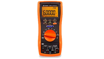
Multimeter Display
The heart of a digital multimeter is its display, where all your measurements come to life in clear, digital form.
Unlike the analog needle, a digital display eliminates guesswork by showing precise readings. Along with numerical measurements, the display includes various symbols and units to convey specific information and measurement types.
Here's a rundown of what you might see:
- V: Volts, the unit of voltage
- A: Amps, the unit of current
- Ω: Ohms, the unit of resistance
- mV: Millivolts, or one-thousandth of a volt
- μA: Microamps, or one-millionth of an amp
- MΩ: Megaohms, or one million ohms
- Hz: Hertz, the unit of frequency
- CAP: Capacitance measurement
- Diode symbol: Indicates diode test function
- Continuity symbol: Often represented as a sound wave, indicating the continuity test function
Dial
The dial, or selection knob, is your command center for selecting the multimeter's functions and ranges.
By turning this knob, you can switch between different modes of measurement—be it voltage (AC/DC), current (AC/DC), resistance, or other specialized functions like capacitance, frequency, and temperature.
Some multimeters feature an auto-ranging function, which automatically selects the appropriate measurement range, while others require manual range selection for accurate readings.
Ports
Understanding the ports on your multimeter is crucial for making correct and safe connections. Common ports include:
- COM (Common): The universal ground or negative port.
- VΩmA: Used for measuring voltage, resistance, continuity, and current up to 200 mA or 250 mA, depending on the model.
- 10A: Dedicated to measuring large currents, up to 10 amperes.
By familiarizing yourself with these basic features, you set the foundation for conducting a wide array of electrical measurements.
How to Select the Correct Function and Range
Selecting the correct function and range on your multimeter is vital to obtaining accurate and meaningful measurements.
Whether you're measuring voltage, current, resistance, or any other electrical parameter, the right settings ensure that your readings are accurate reflections of the electrical phenomena you're investigating.
Importance of Correct Function Selection
Each function on a multimeter is tailored to measure a specific type of electrical quantity. Using the wrong function can lead to incorrect readings or, worse, damage to the multimeter.
For instance, attempting to measure voltage when the multimeter is set to a current measurement mode could blow a fuse in the device or cause harm to the user.
Choosing the Appropriate Range
Once the correct function is selected, choosing the appropriate range is the next step. The range you select determines the multimeter's sensitivity and accuracy for the measurement.
If you're unsure of the expected measurement, start with the highest range and work your way down to avoid overloading the multimeter. This process can be streamlined with the auto-ranging feature available on many digital multimeters.
Auto-ranging multimeters automatically adjust to the optimal range for the detected signal, simplifying the measurement process and reducing the chance of user error. This feature is particularly beneficial for new users or when measuring in rapidly changing conditions.
Auto-Range vs. Manual Range Selection
| Feature | Auto-Range | Manual Range |
|---|---|---|
| Ease of Use | High (Automatic adjustment) | Low (Requires manual selection) |
| Speed | Fast (Instantly finds the correct range) | Varies (Depends on user's ability to select the correct range) |
| Flexibility | High (Adapts to varying signals automatically) | High (Allows precise control over measurement range) |
| Accuracy | Optimized (Automatically selects the most appropriate range) | Dependent on user selection (Correct range selection leads to accurate readings) |
| Suitability | Beginners and professionals in fast-paced or variable environments | Experienced users or applications requiring specific range settings |
Understanding when and how to select the correct function and range is a fundamental skill in using a multimeter effectively.
With practice, you'll find that these decisions become more intuitive, allowing you to make the most of your multimeter's capabilities, whether you're troubleshooting a complex circuit or simply checking battery voltage.

How to Read a Multimeter
Reading a multimeter correctly is a crucial skill that allows you to accurately diagnose and resolve electrical issues. Let's look into the specifics of multimeter measurements.
Measuring Voltage
Measuring voltage, whether AC or DC, is a fundamental task when using a multimeter. Here’s how you can accurately measure both types of voltage, emphasizing the correct settings, multimeter probe placement, and interpretation of the results.
DC Voltage
- Set the dial to DC voltage (often denoted as V- or DCV).
- Insert the black probe into the COM port and the red probe into the VΩmA port.
- Connect the probes across the component or power source you're measuring. The red probe goes to the positive side, and the black probe to the negative.
- Read the display, ensuring you note the unit (volts). A negative sign indicates reverse polarity.
AC Voltage
- Set the dial to AC voltage (usually denoted as V or ACV).
- Insert the probes into the same ports as for DC voltage.
- Probe placement doesn't require polarity matching due to AC voltage's nature.
- The display shows the voltage in volts without a polarity indicator.
Measuring Current
Measuring current with a multimeter requires careful setup, as it involves creating a series connection within the circuit. This means you'll need to open the circuit and insert the multimeter in such a way that the current flows through it.
DC Current
- Set the dial to the DC current setting (A- or DCA).
- For measurements over 200mA, use the 10A port for the red probe; for smaller currents, use the VΩmA port.
- Open the circuit and connect the multimeter in series where you want to measure the current.
- Ensure the display reads in amperes (A), adjusting the range if necessary.
AC Current
- Select the AC current setting (A or ACA) on the dial.
- Follow the same steps as for DC current, noting that polarity is not a concern.
- The readout will be in amperes, indicating the flow of AC current.
Measuring Resistance
Measuring resistance with a multimeter is a straightforward process, crucial for various applications such as checking the continuity of wires, verifying the integrity of components, and ensuring circuits are correctly configured.
Check that the power supply to the component or circuit is disconnected before measuring resistance to prevent damage to the multimeter and ensure the accuracy of the measurement.
- Set the multimeter to the resistance (Ω) setting.
- Insert the black probe into the COM port and the red probe into the VΩmA port.
- Touch the probes to either end of the component or across the circuit section you're testing.
- The display shows the resistance value in ohms (Ω). If the resistance is too high for the selected range, the display may show "OL" or "1," indicating an overload or open circuit.
Measuring Continuity
The continuity test function is a powerful feature of a multimeter that helps you verify if two points in a circuit are electrically connected without any significant resistance. This function is crucial for troubleshooting circuits, checking for breaks in wires, and ensuring connections are solid and reliable.
When a multimeter is set to the continuity test mode, it sends a very small current through the circuit between the test probes. If the circuit is complete (i.e., there's a continuous electrical path), the multimeter will emit an audible beep.
The significance of this beep cannot be overstated—it instantly tells you that electrical current can flow between the points tested, confirming continuity without needing to look at the display.
How to Read the Multimeter When Measuring Continuity
- Set the dial: Turn the multimeter's dial to the continuity test symbol, often represented by a diode symbol or a sound wave icon.
- Insert the probes: Insert the black probe into the COM port and the red probe into the VΩmA port. Probe color does not affect the continuity test, but maintaining consistent color coding helps avoid confusion.
- Test for continuity: Touch the multimeter's probes to the two points you wish to test for continuity. The order doesn't matter since you're checking for a complete circuit, not polarity.
- Listen for the beep: If the multimeter emits a continuous beep, it indicates that the points are electrically connected with very low resistance, signifying good continuity. If there's no beep, it means there's a break in the circuit or the resistance is too high for a continuity reading.
- Reading the display: While the audible beep is the primary indicator in a continuity test, some multimeters also show the resistance value on the display during the test. A very low resistance value (close to 0 ohms) confirms continuity, whereas a high value or an "OL" (overload) reading indicates no continuity.
Diode Testing
Diode testing with a multimeter is a straightforward procedure that helps determine the health of a diode by checking its forward and reverse bias conditions.
Diodes allow current to flow in one direction (forward biased) and block it in the opposite direction (reverse biased).
A healthy diode will show a low resistance (or a voltage drop) in the forward-biased condition and high resistance (or no voltage drop) in the reverse-biased condition.
Procedure for Testing Diodes
- Set the dial: Turn your multimeter's dial to the diode symbol, which typically looks like an arrow striking a line. This setting is designed to measure the forward voltage drop across the diode.
- Insert the probes: Place the black probe in the COM port and the red probe in the VΩmA port. The color coding is crucial here because diode testing depends on the direction of current flow.
- Test forward bias: To test the diode in forward bias, connect the red probe to the anode (positive side) and the black probe to the cathode (negative side) of the diode.
- Test reverse bias: For the reverse bias test, simply reverse the probes—place the red probe on the cathode and the black probe on the anode.
Reading the Multimeter During Diode Testing
- Forward bias condition: In a healthy diode, the multimeter will display a voltage drop typically between 0.5V to 0.8V for silicon diodes and around 0.3V for germanium diodes. This reading confirms that the diode is conducting in the forward direction as expected.
- Reverse bias condition: When the probes are reversed, a good diode will not conduct, and the multimeter should display "OL" or a very high resistance value, indicating no current flow.
Advanced Functions
Advanced multimeters offer a range of additional features beyond the basic multimeter measurements of voltage, current, and resistance.
These features can significantly expand your diagnostic capabilities, allowing for more comprehensive electrical and electronic analysis.
Here's a look at some of these advanced functions, how to use them, and their typical applications.
Capacitance Measurement
- How to use: Select the capacitance mode (often symbolized by a capacitor icon or "Cap"). Connect the probes to the capacitor terminals. Ensure the capacitor is discharged before testing.
- Applications: Checking the capacitance of capacitors in electronic circuits, verifying capacitor health, and ensuring they meet specification values.
Frequency Measurement
- How to use: Set the multimeter to the frequency measurement mode (usually symbolized by "Hz"). Connect the probes to the circuit where frequency measurement is desired.
- Applications: Measuring the frequency of AC signals, verifying oscillator circuit outputs, and troubleshooting signal generators.
Temperature Measurement
- How to use: Some multimeters come with a temperature probe that you plug into a dedicated port. Select the temperature function (often indicated by a thermometer symbol). Insert the temperature probe into the object or area you're measuring.
- Applications: Monitoring the temperature of components and environments, essential for applications sensitive to thermal conditions like HVAC systems and electronics cooling.
Summary Table
| Function | How to Use | Typical Applications |
|---|---|---|
| Capacitance | Switch to Cap mode, connect probes to capacitor terminals | Testing capacitors, verifying health and specification match |
| Frequency | Set to Hz mode, connect probes to signal source | Measuring AC signal frequencies, oscillator output verification |
| Temperature | Select temperature function, use temperature probe | Monitoring component/environment temperature |
These advanced functions extend the utility of a multimeter far beyond basic measurements, enabling professionals and hobbyists alike to tackle a wider array of challenges in electrical and electronic maintenance, troubleshooting, and design.
Learning to use these features can enhance your analytical capabilities, making your multimeter an even more valuable tool in your toolkit.
Understanding and Interpreting Results
Accurately interpreting multimeter readings is essential for diagnosing and solving electrical and electronic issues effectively. Understanding the nuances of the readings, including unit conversions and recognizing common symbols, ensures that you can make informed decisions based on precise data.
For instance, when measuring current, knowing how to convert milliamps (mA) to amps (A) is crucial, (1 A is equal to 1000 mA). This knowledge allows you to understand the scale of the measurement and its implications for the circuit or device you are testing.
Common symbols and abbreviations:
- V – volts,
- A – amperes (or amps)
- Ω – ohms (resistance)
- Hz – hertz (frequency)
- (m) – milli
- (μ) – micro
- (M) – mega
Correctly interpreting these readings and understanding the units and symbols ensures that you can accurately assess the condition of the electrical system or component you're working with.
This accuracy is crucial for troubleshooting, as it leads to more efficient problem-solving and prevents potential errors that could arise from misinterpretation, ensuring the reliability and safety of electrical systems.
Troubleshooting Common Issues
Troubleshooting common issues with multimeters is an essential skill for ensuring accurate and reliable measurements. Inaccurate readings, no readings, or erratic readings can often be traced back to a few common problems. Understanding these issues and knowing how to address them can greatly enhance your multimeter's performance.
Inaccurate Readings
Inaccurate readings can result from improper setting selection, low battery power, or using damaged leads. Make sure you have selected the correct measurement setting and range for your task. Additionally, check the battery level and replace if necessary, as low power can affect accuracy. Regularly inspect your leads for any signs of wear or damage and replace them if needed.
No Readings
If your multimeter shows no readings, it could be due to a blown fuse, incorrect function or range selection, or a problem with the device being tested.
First, check to ensure you're using the correct settings for your measurement. If the issue persists, inspect the fuse and replace it if it's blown.
This is a common issue when attempting to measure current without properly inserting the multimeter in series or exceeding the current rating.
Erratic Readings
Erratic readings can be caused by loose connections, interference from other electrical devices, or a malfunctioning multimeter. Ensure all connections are secure and try to isolate the device from potential sources of interference. If erratic readings continue, the multimeter may need servicing.
Calibration and Maintenance
Regular calibration and maintenance are crucial for ensuring the long-term accuracy and reliability of your multimeter.
Calibration ensures that your multimeter measures within the specified accuracy. Routine maintenance, including cleaning and checking for wear and tear, also plays a critical role in preventing common issues.
Benefits of Keysight’s Calibrated Refurbished Multimeters
Choosing Keysight’s fully tested, calibrated refurbished multimeters is a wise investment. These devices have been rigorously tested and calibrated to meet the same standards as new products, ensuring they provide accurate and reliable measurements.
Opting for a refurbished model not only offers cost savings but also contributes to sustainability by extending the life of high-quality equipment and reducing e-waste.
“For all used equipment, I offer my clients calibration and 1-year warranty.” – Keysight Account Manager
Discover Precision with Keysight's Trusted Premium Used Equipment
Conclusion: Empower Your Electrical Diagnostics Today
Throughout this guide, we've explored the vital role of the multimeter in electrical diagnostics, covering its basic functions, how to select the correct settings, and the steps for accurately measuring voltage, current, resistance, and more.
We've also looked into troubleshooting common issues, emphasizing the importance of regular calibration and maintenance to ensure your multimeter performs reliably over time.
Understanding how to use a multimeter effectively is crucial for anyone involved in electrical work, from professionals to hobbyists. This not only empowers you to diagnose and solve electrical problems efficiently but also enhances safety and accuracy in your projects.
Remember, a high-quality multimeter is a foundation for accurate, reliable diagnostics.
Keysight's selection of rigorously tested, premium used multimeters ensures that precision and reliability accompany every measurement you make.
Investing in one will elevate your electrical diagnostics and equip you with a dependable partner for all your electrical troubleshooting needs. Empower your electrical diagnostics today with the precision and reliability of Keysight.
Whenever You’re Ready, Here Are 5 Ways We Can Help You
- Browse our premium used network analyzers, oscilloscopes, signal analyzers and waveform generators
- Call tech support US: 1 800 829-4444. Press #, then 2. Hours: 7 am – 5 pm MT, Mon– Fri
- Talk to our sales support team by clicking the icon (bottom right corner) on every offer page
- Create an account to get price alerts and access to exclusive waitlists
- Talk to your account manager about your specific needs.