- Introduction
- Decoding Amplitude: Basics and Beyond
- Theoretical Foundations of Amplitude Measurement
- Waveform Analysis
- Mathematical Representation
- Frequency and Amplitude
- Practical Guide to Measuring Amplitude
- Essential Tools and Equipment
- Step-by-Step Measurement Procedure
- Advanced Measurement Techniques
- Navigating Common Challenges in Amplitude Measurement
- Signal Interference
- Equipment Limitations
- Environmental Factors
- Calibration and Maintenance of Measuring Equipment
- Real-World Applications: Amplitude in Action
- Amplitude in Telecommunications
- Audio Engineering and Amplitude
- Medical Equipment and Diagnostics
- Conclusion: Amplify Your Engineering Expertise With Keysight
- Whenever You’re Ready, Here Are 5 Ways We Can Help You
Imagine you are working on the latest satellite technology. Each component and every signal you handle must be precise. A single error in your measurements, and the satellite might fail to communicate with Earth.
In this intricate work, the amplitude of electronic signals becomes critical, highlighting the importance of amplitude measurement in the vast realm of engineering.
As we go through this guide, we will explore the various applications of amplitude measurement. From fine-tuning communication systems and designing resilient structures to improving audio equipment.
Decoding Amplitude: Basics and Beyond
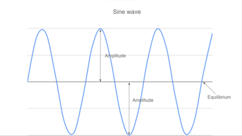
Amplitude, in the realm of wave theory, is the height of a wave from its equilibrium point to its peak. It's the measure of the wave's intensity or strength.
When we speak of waves, think of them as ripples on a pond or sound waves emanating from a speaker. The amplitude is the distance between the baseline of the wave (where it would be at rest) and its highest point (the crest) or lowest point (the trough).
To better understand this, let's look at a simple diagram showing amplitude in different waveforms:
Amplitude plays a crucial role in determining signal strength and quality. In telecommunications, for example, a signal with greater amplitude carries more power and can travel further distances. Similarly, in audio engineering, amplitude influences the loudness of sounds. Higher amplitude results in louder sounds, while lower amplitude corresponds to softer sounds.
Key aspects of amplitude in wave theory include:
- Definition: The maximum extent of a wave measured from its equilibrium.
- Unit of measurement: Often measured in decibels (dB) for sound waves or volts for electrical signals.
- Influence on signal quality: Higher amplitude can improve signal quality but may also introduce distortion if not managed properly.
- Role in different waves: In sound waves, amplitude relates to loudness; in light waves, it's tied to brightness; in electrical signals, it denotes signal strength.
- Manipulation in engineering: Engineers often manipulate amplitude in signal processing, audio engineering, and broadcasting to achieve desired outcomes.
Understanding amplitude and its implications is crucial for engineers and scientists working with any form of wave, whether they're dealing with sound, light, electricity, or other waveforms.
Theoretical Foundations of Amplitude Measurement
Amplitude measurement is a cornerstone in the understanding and application of wave theory, playing a pivotal role in various scientific and engineering disciplines.
Grasping the concept of amplitude requires a deep dive into waveform analysis, as different types of waveforms exhibit unique amplitude characteristics.
Waveform Analysis
Sine Waves
- Description: A smooth, periodic oscillation that is fundamental in wave theory.
- Amplitude: The peak value of the wave, often represented as the height from the center line to the peak.
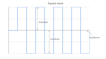
Square Waves
- Description: Characterized by their abrupt transitions between high and low values, resembling a square.
- Amplitude: The maximum value of the wave, equal in both positive and negative directions from the center line.
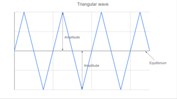
Triangle Waves
- Description: A waveform with linear rises and falls, forming a triangular shape.
- Amplitude: Similar to sine waves, the peak value from the center to the highest or lowest point.
Sawtooth Waves
- Description: Resembles the teeth of a saw, with a gradual rise and a sharp fall (or vice versa).
- Amplitude: Defined by the extreme values reached before the wave abruptly changes direction.
Pulse Waves
- Description: Similar to square waves but with unequal time spent at the high and low amplitudes.
- Amplitude: The amplitude is the maximum value achieved during the pulse.
Waveform Comparisons
| Waveform Type | Shape Description | Amplitude Description |
|---|---|---|
| Sine | Smooth, periodic oscillation | Peak value from center to peak |
| Square | Abrupt high and low transitions | Maximum value, same in both directions |
| Triangle | Linear rise and fall | Peak value from center to highest/lowest point |
| Sawtooth | Gradual rise and sharp fall (or vice versa) | Extreme values before direction change |
| Pulse | Unequal high and low durations | Maximum value during the pulse |
This analysis provides a clear understanding of how amplitude varies across different waveforms, each with its unique characteristics and applications.
Mathematical Representation
The mathematical representation of amplitude is crucial for quantifying and analyzing waveforms accurately. There are several key models used to represent amplitude, each serving a specific purpose depending on the context of the analysis.
- Peak amplitude (A): This is the maximum value (positive or negative) that the waveform reaches. It is the absolute value of the height from the equilibrium (zero) level to the peak of the wave.
- Peak-to-Peak amplitude (A_pp): This measures the total height of the wave, calculated as the difference between its maximum and minimum values. It's especially useful in contexts where the entire range of the wave is important, like in alternating current (AC) circuits.
- Root-mean-square (RMS) amplitude: RMS amplitude provides a measure of the effective value of the waveform. It's particularly relevant for power calculations, as it gives the DC-equivalent value. The RMS value of a waveform is the square root of the average of the squares of the values.
Here are some sample calculations for these models:
Sine Wave:
- Peak Amplitude: A = max(sin(θ))
- Peak-to-Peak Amplitude: App = 2 * A
- RMS Amplitude: ARMS = A/\(\sqrt{2}\)
Square Wave:
- Peak Amplitude: A = max(value of square wave)
- Peak-to-Peak Amplitude: App = 2 * A
- RMS Amplitude: ARMS = A (since the square wave maintains a constant amplitude)
Triangle Wave:
- Peak Amplitude: A = max(value of triangle wave)
- Peak-to-Peak Amplitude: App = 2 * A
- RMS Amplitude: ARMS = A /\(\sqrt{3}\)
These mathematical models provide a framework for engineers and scientists to analyze and interpret waveforms accurately, ensuring precise measurements and effective application in various contexts.
Frequency and Amplitude
The relationship between frequency and amplitude is fundamental in understanding signal characteristics in various fields, from audio engineering to telecommunications. While these two properties are distinct, their interplay significantly affects the overall behavior and perception of a signal.
- Frequency: This refers to the number of cycles a waveform completes in a given time period, usually measured in Hertz (Hz). It determines the 'pitch' of a sound in audio applications or the rate of oscillation in electrical signals.
- Amplitude: As previously discussed, amplitude measures the strength or intensity of the signal, influencing volume in sound waves or signal power in electrical contexts.
The combined effect of frequency and amplitude can be summarized as follows:
- Perception of sound: In audio, a higher frequency will be perceived as a higher-pitched sound, while the amplitude controls how loud this sound appears. A low-frequency sound at the same amplitude will be perceived as lower in pitch at the same intensity.
- Signal transmission: In telecommunications, both frequency and amplitude are crucial. Higher frequency signals can carry more data, but they may also be more susceptible to interference. Amplitude, on the other hand, affects the range and strength of the transmission but can introduce noise if too high.
- Power distribution: In electrical engineering, the product of frequency and amplitude can determine the power transmitted by a signal. Higher amplitudes mean more power, but this needs to be balanced with the right frequency for efficient transmission and to avoid system damages.
- Harmonic content: The frequency of a signal defines its basic tone, while its harmonics (multiples of the fundamental frequency) shapes the timbre or color of the sound in audio applications.
In essence, while frequency determines the rate of oscillation of a signal, amplitude dictates its strength or intensity. Their interaction is a dance of balance, with each playing a critical role in defining the signal's characteristics and its suitability for various applications.
Understanding this interplay is key for engineers and scientists in designing systems and solutions that effectively leverage the properties of both frequency and amplitude.
Practical Guide to Measuring Amplitude
In the practical world of engineering and science, accurately measuring amplitude is a critical task that requires specific tools and equipment. The right choice of instruments not only ensures precision, but also enhances efficiency and reliability in various applications, from electronic circuit design to acoustic engineering.
In this section, we will explore the essential tools commonly used for amplitude measurement, focusing on their specific roles and functionalities.
Essential Tools and Equipment
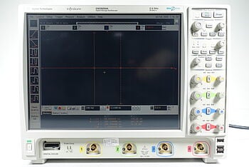
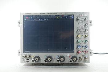
Oscilloscopes
- Role: An oscilloscope is indispensable for visualizing and measuring the waveform of electronic signals. It displays amplitude versus time, allowing for real-time observation of signal characteristics.
- Use cases: Ideal for detailed analysis of waveform shapes, frequency, and amplitude in electronic circuits.
Multimeters
- Role: Multimeters measure voltage, current, and resistance. While not as detailed as oscilloscopes, they are crucial for quick and accurate amplitude measurements in electrical systems.
- Use cases: Best suited for basic amplitude measurement tasks, like checking battery voltage or diagnosing simple circuit issues.
Spectrum Analyzers
- Role: Spectrum analyzers are used to analyze the frequency spectrum of a signal, offering insights into amplitude at different frequencies.
- Use cases: Essential in applications involving complex signals, such as radio frequency analysis and audio engineering.
Function Generators
- Role: Although primarily used to generate signals of varying frequencies, amplitudes, and waveforms, they also aid in testing and calibration of electronic equipment.
- Use cases: Useful in creating test signals to assess the performance of audio systems, filters, and electronic circuits.
Let's compare these devices in a table:
| Device | Primary Function | Key Features | Ideal Use Case |
|---|---|---|---|
| Oscilloscope | Visualizing waveforms | Real-time waveform display, detailed analysis | Electronic signal analysis, circuit testing |
| Multimeter | Measuring voltage, current | Portability, ease of use | Basic electrical measurements, diagnostics |
| Spectrum Analyzer | Analyzing frequency spectrum | Detailed frequency analysis | RF systems, audio frequency analysis |
| Function Generator | Generating test signals | Adjustable frequency and amplitude | Equipment testing, signal generation |
Each of these tools plays a specific role in the process of amplitude measurement, and the choice of tool depends on the complexity of the task and the level of detail required.
Step-by-Step Measurement Procedure
Measuring amplitude can vary based on the context and equipment used. Here's a general guide that can be applied to most scenarios:
- Select the right tool: Choose an oscilloscope, multimeter, or another appropriate device based on the specific requirements of your measurement task.
- Connect the device: Safely connect your measurement tool to the signal source. For oscilloscopes, this typically involves connecting the probe to the point in the circuit where you want to measure the signal.
- Configure the device: Set up the device according to the type of signal you're measuring. For example, on an oscilloscope, adjust the time base and voltage per division settings to suit the expected signal amplitude and frequency.
- Observe the signal: Carefully observe the waveform displayed on the oscilloscope or read the measurement on the multimeter.
- Record the measurement: Note down the amplitude reading. On an oscilloscope, this may involve measuring the vertical distance from the peak to the trough (or to the baseline for peak amplitude).
- Repeat and average: To increase accuracy, repeat the measurement several times and calculate an average value.
Tips for Accuracy and Precision:
- Ensure your device is calibrated correctly before starting measurements.
- Use probes and cables of good quality to avoid signal degradation.
- Be mindful of the bandwidth of your measuring device; it should be appropriate for the frequency of the signal being measured.
- Avoid external interference that might distort the signal, like electromagnetic noise or physical vibrations.
- In noisy environments, use averaging functions if available on your device to get a more accurate reading.
Advanced Measurement Techniques
In more complex scenarios, the need for advanced measurement techniques is paramount.
- Fast Fourier Transforms (FFT): FFT is a mathematical approach that converts a time-domain signal into its constituent frequency components, making it invaluable for analyzing the amplitude of various frequencies within a complex signal. This technique finds widespread application in areas such as audio signal processing, vibration analysis, and telecommunications.
- Time-Domain Reflectometry (TDR): TDR is instrumental in characterizing and pinpointing faults in cables and transmission lines. By sending a pulse along the cable and examining the reflected signal, TDR can provide insights into impedance changes and detect faults through the analysis of the amplitude of the reflected signal.
- Digital Signal Processing (DSP): DSP encompasses a range of techniques for analyzing, modifying, and synthesizing digital signals. This includes processes such as filtering, modulation, and demodulation, which often rely on FFT for in-depth frequency analysis. DSP is fundamental in numerous fields, including digital audio, communications, and image processing.
These advanced measurement techniques significantly broaden the possibilities of amplitude measurement, enabling more precise and specific analyses in intricate scenarios. For professionals in fields where signal integrity and comprehensive analysis are critical, mastering these techniques is of utmost importance.
Navigating Common Challenges in Amplitude Measurement
Amplitude measurement, though essential, is not without its challenges. Various factors can affect the accuracy and reliability of measurements, from signal interference to environmental influences. Understanding these challenges and knowing how to navigate them is crucial for anyone involved in the precise measurement of amplitude.
Signal Interference
Signal interference can significantly distort the accuracy of amplitude measurements. It's crucial to first identify the source of interference and then apply appropriate mitigation strategies.
Common Sources of Interference:
- Electromagnetic Interference (EMI) from nearby electronic devices.
- Radio Frequency Interference (RFI) from wireless transmitters.
- Power line noise, especially in industrial environments.
- Cross-talk from other signal lines.
Mitigation Strategies:
- Use shielded cables and proper grounding to reduce EMI.
- Maintain a distance from or shield against known sources of RFI.
- Implement filters to isolate the desired signal frequency.
- Separate signal lines and use twisted-pair cables to minimize cross-talk.
Equipment Limitations
Understanding and working within the limits of your measuring equipment is vital to ensure accuracy.
Considerations:
- Be aware of the bandwidth and frequency range of your equipment.
- Understand the resolution and sensitivity of the device.
- Regularly calibrate your equipment to maintain accuracy.
Strategies:
- Choose the right tool for the specific measurement task.
- Avoid pushing the equipment beyond its specified limits.
- When in doubt, consult the equipment’s manual or seek expert advice.
Environmental Factors
Environmental factors like temperature, humidity, and atmospheric pressure can affect amplitude measurements. Compensating for these factors is often necessary for precise readings.
Impact on Measurements:
- Temperature changes can affect the resistance of components, altering signal strength.
- High humidity can lead to condensation and short-circuits in electronic systems.
- Atmospheric pressure changes can influence sensitive measurement equipment.
Compensation Techniques:
- Use temperature-compensated equipment where possible.
- Control the measurement environment, keeping it dry and at a stable temperature.
- Account for environmental factors in your calculations or use equipment that automatically compensates for them.
By addressing these common challenges, you can significantly enhance the accuracy and reliability of your amplitude measurements.
Calibration and Maintenance of Measuring Equipment
The reliability of amplitude measurements heavily depends on the precision and accuracy of the measuring tools like oscilloscopes, multimeters, and signal analyzers.
Regular calibration and maintenance of these instruments are pivotal in ensuring their performance and accuracy. Calibration aligns the measurements of the instrument with known standards, ensuring that the readings are accurate and reliable.
Importance of Calibration and Maintenance
- Accuracy and reliability: Calibration ensures that measurements are consistent with other measurements or standards. This is crucial in fields where precision is paramount, such as in scientific research, manufacturing, and quality control.
- Compliance with standards: Many industries have regulatory requirements that mandate periodic calibration of measurement tools to ensure safety and quality.
- Prevention of errors: Regular maintenance and calibration can identify and correct issues before they lead to significant errors or equipment failures.
Guidelines for Calibration and Maintenance
1. Calibration frequency:
- The frequency of calibration depends on the usage and the environment in which the equipment is used. High-precision environments or heavy usage typically require more frequent calibration.
- A general rule of thumb is to calibrate measurement equipment at least once a year. However, refer to the manufacturer’s recommendations and industry standards for specific guidance.
2. Signs calibration is needed:
- Inconsistent or erratic readings that deviate from expected results.
- Physical damage to the device, such as a dropped or bumped oscilloscope.
- After a significant change in the operating environment, like a large temperature shift.
- When the instrument has been used extensively and has not been calibrated for an extended period.
Meet All Your Calibration Service Needs with Keysight
Keysight's comprehensive calibration services are designed to meet the diverse needs of professionals in various industries. With their commitment to precision, multi-brand support, and compliance, Keysight ensures that your instruments deliver accurate and reliable performance. Their services encompass a wide range of features to cater to all your calibration requirements.
Precise Calibration for Every Specification
- Keysight instrument calibration: Every specification, option, and detail is calibrated to ensure your test system performs exactly to its intended specifications.
One-Stop Calibration Services for All Brands
- Multi-brand support: Keysight offers calibration services not just for their own products but for other brands as well. Schedule calibrations every 6, 12, 24, or 36 months to maintain peak performance of all your test equipment.
Standards Lab Calibration for Accurate Measurements
- High accuracy standards: By comparing your devices to primary or reference standards, Keysight ensures the highest level of accuracy, essential for precise measurements in critical applications.
Antenna Calibration for Compliance
- Compliance with standards: Receive calibration services that are compliant with standards, ensuring SI-traceable results for a wide range of applications, from radio and radar to EMI/EMC testing.
Extended Service for Longevity
- Maintaining legacy instruments: Keysight helps in keeping long-term programs and older instruments operational, allowing you to transition to new technology at your own pace.
Global and Local (Glocal) ISO/IEC 17025 Accreditation
- Global and local accreditation: Keysight's calibration services are accredited by a selection of local bodies, including JCSS, CNAS, UKAS, and ANAB, meeting both global and local requirements.
Regular calibration and maintenance with Keysight's services are more than routine checks; they are an investment in the integrity and longevity of your equipment.
By utilizing Keysight's state-of-the-art techniques and expertise, you can ensure that your instruments remain in top condition, delivering precise and reliable results that are vital for the success and safety of your projects and research endeavors.
Real-World Applications: Amplitude in Action
Amplitude is more than just a theoretical concept; it finds extensive practical application in various real-world scenarios. From the clarity of a phone call to the precision of medical diagnostics, the role of amplitude is both varied and vital.
Understanding how amplitude operates in different domains offers insights into its universal importance across multiple industries.
Amplitude in Telecommunications
In the realm of telecommunications, amplitude plays a pivotal role in determining signal quality. It's the measure of signal strength – the higher the amplitude, the stronger the signal. This strength is crucial for clear voice and data transmission over distances.
In technologies like amplitude modulation (AM), the amplitude of the carrier wave is varied in proportion to the information or message signal. However, high amplitude signals are more prone to noise and interference, making it a delicate balance to maintain optimal signal quality.
Effective amplitude control and measurement are key to ensuring reliable communication in everything from mobile networks to satellite transmissions.
Audio Engineering and Amplitude
In audio engineering, amplitude directly impacts the loudness and clarity of sound. The amplitude of sound waves determines how loud or soft the sound is perceived. In recording studios, concert halls, and even in home audio systems, managing amplitude is essential for achieving the desired sound quality.
Sound engineers routinely adjust amplitude levels to balance different elements of a track or performance, ensuring that each note is heard clearly without distortion.
The precise control of amplitude is also vital in sound design, where it contributes to creating the desired mood or effect in various media, from movies to video games.
Medical Equipment and Diagnostics
In the field of medical technology, amplitude measurement finds its use in various diagnostic and therapeutic equipment. For example, in electrocardiograms (ECG), the amplitude of the electrical signals produced by the heart provides critical information about cardiac health.
Similarly, in ultrasound imaging, the amplitude of sound waves is used to create images of internal body structures. The ability to accurately measure and interpret amplitude in these applications is crucial for correct diagnosis and effective treatment.
Conclusion: Amplify Your Engineering Expertise With Keysight
Throughout this guide, we have explored the multifaceted world of amplitude measurement, highlighting its crucial role in various engineering fields. From telecommunications and audio engineering to medical diagnostics, the accurate measurement and management of amplitude are integral to the success and effectiveness of numerous applications.
Some key points to remember include understanding the different forms of amplitude—peak, peak-to-peak, and RMS—and their applications, recognizing the importance of tools like oscilloscopes and multimeters, and appreciating the nuances of advanced measurement techniques like FFT and TDR.
We've also discussed the impact of external factors like signal interference and environmental conditions, and the imperative of regular calibration and maintenance, services expertly provided by Keysight.
As you apply these insights into your engineering practices, remember that mastering amplitude measurement is more than just comprehending wave theory. It's about enhancing your capacity to create, innovate, and optimize in your field.
With the right knowledge, tools, and support from leaders like Keysight, you are well-equipped to unlock the full potential of your engineering projects.
"Mastering amplitude measurement is not just about understanding waves; it's about unlocking potential in your engineering projects."
Whenever You’re Ready, Here Are 5 Ways We Can Help You
- Browse our premium used network analyzers, oscilloscopes, signal analyzers and waveform generators.
- Call tech support US: 1 800 829-4444
Press #, then 2. Hours: 7am – 5pm MT, Mon– Fri - Talk to our sales support team by clicking the icon (bottom right corner) on every offer page
- Create an account to get price alerts and access to exclusive waitlists.
- Talk to your account manager about your specific needs