- Introduction
- What Is Return Loss?
- Return Loss and VSWR
- Why Is Return Loss an Important Measurement?
- How To Measure Return Loss
- Equipment You Will Need
- Step-By-Step Guide
- Understanding the Measurements
- Buy a Keysight Spectrum Analyzer and save up to 90%
- Closing Thoughts From Keysight
- Why Should You Buy Premium Used From Keysight?
- Whenever You’re Ready, Here Are 4 Ways We Can Help You
As an engineer, dealing with reflections is one of the most frustrating problems. Whether it's a reflection of a mismatched load or a faulty connector, these reflections can impede the correct functioning of a system.
Reflections interfere with the signal and can also give false readings on the spectrum analyzer, leading to incorrect results and wasted time trying to troubleshoot the issue. It's a problem almost every engineer has faced at some point in their career, and it can be a real headache to deal with.
This article will clearly explain some of the most common sources of return loss and how to minimize their effect on your measurements. We will also examine how you can ensure an accurate readout from your spectrum analyzer when measuring return loss, avoiding time-consuming troubleshooting due to faulty readings.
What Is Return Loss?
Return loss is a measure of the amount of power reflected back to the source due to an impedance mismatch in a transmission system. You express return loss in decibels (dB) using the following formula.
Return Loss (dB) = -20 * log10(|S11|)
Where |S11| is the magnitude of the reflection coefficient. The reflection coefficient measures the ratio of the reflected wave to the incident wave at a given point in the transmission system.
A high return loss indicates a good impedance match, with little incoming signal power reflected back to the source. A low return loss means an impedance mismatch, resulting in a significant amount of incoming signal power reflected back to the source.
In a transmission system, the transmission line impedance must match the load impedance to minimize reflections. If it's not, the impedance mismatches and a portion of the incident wave reflects back to the source. A reflection coefficient quantifies this reflected wave:
Γ = (ZL – Z0) / (ZL + Z0)
ZL is the load impedance, and Z0 is the transmission line's characteristic impedance. The magnitude of the reflection coefficient, |Γ|, is the ratio of the reflected wave to the incident wave and is a measure of the strength of the reflection.
The return loss is then calculated by taking the magnitude of the reflection coefficient and converting it to dB using the first formula.
There are several possible causes of typical return loss that you may encounter.
- Signal reflection. When a signal travels through a transmission line, it reflects back to the source if it encounters a change in the characteristics of the transmission line, such as a change in impedance. This can occur if the transmission line is terminated in an impedance different from its characteristic impedance or if there is a fault or discontinuity.
- Discontinuities. A discontinuity in a transmission line is any location where the characteristics of the line change abruptly. This can include connectors, splices, or bends in the line. Discontinuities cause reflections and result in a low return loss.
- Impedance mismatches. An impedance mismatch occurs when the transmission line impedance does not match the load's impedance. This causes reflections and results in a low return loss.
Return loss is an important parameter to measure in transmission systems because it can affect the system's performance. For example, a high loss indicates that the transmission line is operating efficiently. In contrast, a low loss indicates that the transmission line is not operating at its full potential.
Return Loss and VSWR
Voltage Standing Wave Ratio (VSWR) is the ratio between the maximum voltage and the minimum voltage of the standing wave pattern on a transmission line. The standing wave pattern results from the interaction between the incident wave and the reflected wave on a transmission line.
VSWR evaluates the performance of transmission lines and antennas. VSWR is expressed as a ratio, with a value of 1 indicating a perfect match between the transmission line and the load. A value greater than 1 indicates an impedance mismatch, which can result in reflections and a low return loss.
You calculate VSWR by using the following formula.
VSWR = (1 + |Γ|) / (1 – |Γ|)
One key difference between return loss and VSWR is how you calculate them. You calculate return loss by using the reflection coefficient, which measures the ratio of the reflected wave to the incident wave at a given point in the transmission system. On the other hand, you calculate VSWR by using the maximum and minimum voltage levels of the standing wave pattern on a transmission line.
Another difference is how they are expressed. Return loss is always expressed in dB, while VSWR is a ratio. A high loss corresponds to a low level of reflection. In contrast, a low loss corresponds to a high level of reflection.
Similarly, a VSWR close to 1 corresponds to a good impedance match and a low level of reflection. In contrast, a high VSWR corresponds to a poor impedance match and a high level of reflection.
Despite these differences, return loss and VSWR evaluates the performance of transmission systems. Both can provide valuable information about the level of reflections in a system and identify and correct any issues affecting its performance.
There are a few reasons why return loss is the preferable specification when evaluating the performance of a transmission system.
- It is a more direct measure of reflections. You calculate return loss using the reflection coefficient, which measures the ratio of the reflected wave to the incident wave at a given point in the transmission system. This makes it a more direct measure of reflections than VSWR.
- It is expressed in dB. Return loss is always expressed in dB, which is a logarithmic scale. This can make it easier to interpret and compare the results of different measurements, as the dB scale compresses large differences into a smaller range.
- It can be more sensitive to small changes. Because return loss is expressed in dB, it can be more sensitive to small changes in the level of reflections. This can make it a more helpful specification for identifying and troubleshooting issues in a transmission system.
Why Is Return Loss an Important Measurement?
Return loss is an important measurement to understand as it can affect different aspects of a transmission system.
| Affects | Meaning |
|---|---|
| Impedance levels | Return loss is closely related to the impedance levels of a transmission system. A high loss indicates a good impedance match, while a low loss indicates a poor impedance match. |
| Amplitude variations | Reflections can cause amplitude variations in the signal, resulting in signal distortion and reduced transmission efficiency. By minimizing reflections through a high return loss, it is possible to reduce the impact of amplitude variations and improve the performance of the transmission system. |
| Antenna measurements and tuning | Return loss is an important parameter when tuning an antenna. A high loss indicates a good impedance match between the antenna and the transmission line, which can improve the antenna's performance. |
| Filter measurements | Return loss is also an important parameter to consider when measuring the performance of filters. A high loss indicates that the filter operates efficiently and can reject unwanted signals. In contrast, a low loss may indicate that the filter is not functioning correctly. |
Overall, return loss is an important parameter to measure in a transmission system because it can affect its performance. By minimizing reflections through a high return loss, it is possible to improve the performance and reliability of the system and ensure that it is operating at its full potential.
How To Measure Return Loss
You measure return loss using a vector network analyzer (VNA) or a spectrum analyzer (SA).
- A VNA is a specialized instrument specifically designed to measure the electrical characteristics of transmission systems. It can measure various parameters, including return loss, impedance, insertion loss, and phase shift. You use VNAs in research and development, manufacturing, and quality control applications since it has high accuracy and precision.
- A SA is another electronic test instrument used to measure the frequency and amplitude of a signal. It measures the spectral content of a signal and parameters such as return loss and signal-to-noise ratio. You use SAs in various applications, including spectrum monitoring, interference, and signal analysis.
VNAs and SAs are helpful tools to calculate reflection measurements and return loss, and the choice of which one to use depends on the specific needs and requirements of the application.
VNAs are often the preferred choice for applications that require high accuracy and precision, such as research and development, manufacturing, and quality control. They are also helpful for measuring complex transmission systems with multiple ports or frequency-dependent characteristics.
There are a few reasons why using a SA may be more beneficial for taking return loss measurements.
- Simplicity. Simpler to use and require less setup than VNAs, SAs are a good choice for users who may not be familiar with more advanced measurement equipment.
- Portability. Smaller and more portable than VNAs, SAs are easier to take on-site for field measurements.
- Cost. Less expensive than VNAs, SAs are an affordable option for users who may not need the advanced capabilities of a VNA.
- Ease of use. Easier to use than VNAs, SAs have a more intuitive interface and fewer controls. This can make them a good choice for users who may not need the advanced capabilities of a VNA.
Today's modern spectrum analyzers are useful tools for measuring return loss and are a good choice for users who need a portable, easy-to-use measurement tool.
Equipment You Will Need
Here is a list of the equipment you will need to measure return loss using a spectrum analyzer (SA).
- Calibration kit. A calibration kit, also known as a calibration standard, is a set of known standards used to calibrate the measurement system. Calibration is essential to ensure accurate measurements.
- Connectors and cables. You will need a variety of connectors and cables to connect the spectrum analyzer to your transmission system and the calibration kit to the spectrum analyzer.
- Adapter. Depending on the connectors and cables that you have available, you may need an adapter to connect the spectrum analyzer to your transmission system.
- Power supply. You will need a power supply to power the spectrum analyzer and any other equipment you use.
- Computer. Depending on the spectrum analyzer you use, you may need a computer to run the measurement software and view and analyze the measurement results.
- Software. You will need software to control the spectrum analyzer and to view and analyze the measurement results. This software will either come with the spectrum analyzer or be purchased separately.
Step-By-Step Guide
Now that you know what you need for a return loss measurement setup, here is a step-by-step guide on how to take the measurements using a spectrum analyzer (SA).
- Calibrate the measurement system. Use the calibration kit to calibrate the measurement system. This is important to ensure the accuracy and precision of the measurements.
- Connect the spectrum analyzer. Use the appropriate connectors and cables to connect the spectrum analyzer to your transmission system. Depending on the connectors and cables that you have available, you may need to use an adapter.
- Configure the measurement settings. Use the measurement software to configure the measurement settings, including the frequency range, resolution bandwidth, and other necessary parameters.
- Take the measurement. Use the measurement software to initiate the measurement and capture the return loss data.
- Analyze the measurement results. Use the measurement software to view and analyze the measurement results. Look for any anomalies or deviations in the measurement data that may indicate a problem with the transmission system.
- Save the measurement data. Save the data so you can review it later or compare it to future measurements.
- Disconnect the spectrum analyzer. After taking the measurement, disconnect the spectrum analyzer from the transmission system and turn it off.
Taking return loss measurements with a spectrum analyzer is a relatively simple process. By having the right equipment and following these steps, you can ensure that you can take accurate measurements and get the most out of your spectrum analyzer.
Understanding the Measurements
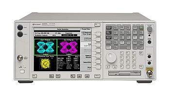
When taking return loss measurements with a spectrum analyzer, the measurement results are displayed as a graph or chart showing the return loss at different frequencies. The x-axis of the graph will represent the frequency of the signal. The y-axis represents the return loss in decibels (dB).
A high return loss measurement indicates that there is a good impedance match in the transmission system and that there are relatively low levels of reflections. This is desirable, as it can result in better performance and reliability of the transmission system.
A low return loss measurement, on the other hand, indicates that there is a poor impedance match in the transmission system and that there are relatively high levels of reflections. This can result in signal distortion, reduced transmission efficiency, and other issues that can affect the performance of the transmission system.
By analyzing the measurement results, it is possible to identify any issues affecting the transmission system's return loss and take corrective action as needed.
Buy a Keysight Spectrum Analyzer and save up to 90%
Return loss is an important parameter to consider when designing and maintaining a transmission system, as it affects the performance and reliability of the system. By measuring the return loss of a transmission system using a spectrum analyzer from Keysight, you can be sure that you will get accurate and precise measurement results every time!
So if you are experiencing problems with return loss in your transmission system, then don't wait; purchase a premium used Keysight spectrum analyzer today! With our unbeatable prices and reliability, you can save up to 90% off the retail price.
Don't miss out – get your spectrum analyzer now and ensure that your transmission system is operating at its full potential and delivering the best possible performance.
Closing Thoughts From Keysight
Taking return loss measurements is important when assessing a transmission systems' performance and reliability. With the proper test equipment, you can quickly and accurately measure the return loss of your system and identify any issues affecting its performance.
Get ahead of any potential problems by taking return loss measurements using a high-quality Keysight spectrum analyzer. Doing so ensures that your transmission system operates at its full potential and delivers the best performance. Check out our used equipment, purchase a Keysight Spectrum Analyzer, and take return loss measurements today!
Why Should You Buy Premium Used From Keysight?
We are the only company that can provide calibration of your premium used spectrum analyzer. That means you can get straight to work using a reliable and accurate device of the highest standard.
We offer a fast two-week delivery time* for selected spectrum analyzers, which is 6-19 weeks faster than other resellers.
We provide an upgradable warranty, giving you peace of mind knowing you are getting a quality product backed by a trusted manufacturer. Call 1-800-829-4444 and ask to speak to tech support today.
See Keysights Used Equipment for the widest selection of discounted, high-quality, refurbished spectrum analyzers.
* Two weeks shipping time offer available for US customers only. Dependent on item availability and location.
Whenever You’re Ready, Here Are 4 Ways We Can Help You
- Browse our premium used spectrum analyzer offers
- Call tech support US: 1 800 829-4444
Press #, then 2. Hours: 7 am – 5 pm MT, Mon– Fri - Talk to our sales support team by clicking the icon (bottom right corner) on every offer page
- Talk to your account manager about your specific needs