- Introduction
- Introduction to Kirchhoff's Laws
- An In-depth Look at Kirchhoff's Voltage Law (KVL)
- Empower Your Innovations with Keysight's Refurbished Solutions
- Mathematical Formulation of KVL
- Application of KVL in Circuit Analysis
- How to Solve Circuits with KVL
- Step-by-Step Guide
- KVL in AC Circuits
- Practical Considerations and Limitations of KVL
- Advanced Applications of KVL in Electrical Engineering
- Troubleshooting and Common Mistakes
- Strategies for Verifying Accuracy
- The Role of Measurement and Testing Equipment in Applying KVL
- Maximize Your Budget without Compromising Quality with Keysight
- Conclusion: Empower Your Circuit Analysis with Keysight's Precision Tools
- Whenever You’re Ready, Here Are 5 Ways We Can Help You
Do you find it frustrating when you spend hours on a difficult circuit problem, only to realize you can't figure it out?
Or when the neat, clean theories from textbooks don’t match up with the messy, unpredictable results in the real world? It feels like hitting a wall, doesn't it?
But what if there was a way to solve complex circuits with a more systematic approach?
Kirchhoff's Laws (KVL) are a cornerstone of electrical engineering and circuit theory. These laws, formulated by Gustav Kirchhoff in the mid-19th century, offer a powerful set of tools for analyzing circuits.
They allow engineers to predict how current and voltage distribute themselves in electrical networks. Bridging the gap between theory and the often unruly nature of real-world applications.
By understanding and applying Kirchhoff's Laws, you'll be able to solve complex circuit problems more efficiently, aligning theoretical predictions with actual outcomes.
This will help bridge the gap between theory and practice and enhance your skill set, making you a more competent and confident engineer.
So, if you're ready to turn your frustration into success and crack the code of complex circuits, let’s explore Kirchhoff's Voltage Law together.
Introduction to Kirchhoff's Laws
Kirchhoff's Laws, formulated by Gustav Kirchhoff in 1845, are two rules that are fundamental to circuit analysis and electrical engineering.
These laws, known as Kirchhoff's Current Law (KCL) and Kirchhoff's Voltage Law (KVL), provide a framework for understanding how currents and voltages behave in electrical circuits.
- Kirchhoff's Current Law (KCL) states that the total current entering a junction in a circuit equals the total current leaving the node. This law is rooted in the principle of conservation of electric charge, ensuring that no charge is lost or created within a circuit.
- Kirchhoff's Voltage Law (KVL) asserts that the sum of the electrical potential differences around any closed loop or network is zero. This law is based on the conservation of energy, implying that the total energy around a loop is conserved, with no net loss or gain.
These laws are crucial for analyzing both simple and complex circuits, allowing engineers to calculate unknown values within a network and ensuring the accurate design and operation of electrical systems.
| Aspect | Kirchhoff's Current Law (KCL) | Kirchhoff's Voltage Law (KVL) |
| Principle | Conservation of electric charge | Conservation of energy |
| Statement | The sum of currents entering a node equals the sum of currents leaving the node. | The sum of voltages around a loop equals zero. |
| Application | Used to analyze current flow in junctions and networks. | Used to analyze voltage drops and gains in closed loops. |
| Key Use | Determining the distribution of current in circuits. | Calculating the potential differences in circuits. |
Gustav Kirchhoff's development of these laws in the mid-19th century marked a significant advancement in electrical engineering, providing a solid foundation for both theoretical analysis and practical application in circuit design. Their fundamental role in the field cannot be overstated.
An In-depth Look at Kirchhoff's Voltage Law (KVL)
The essence of KVL is rooted in the principle of energy conservation. Voltage, in the context of electrical circuits, represents the potential energy per unit charge.
As electrical charges traverse a circuit, passing through various components like batteries and resistors, the total energy of the charges by the time they complete the loop and return to their starting point must remain unchanged.
This foundational principle ensures that the circuit, as a closed system, maintains energy equilibrium, with no net loss or gain.
To visualize KVL in action, consider a basic circuit consisting of a battery and a resistor within a closed loop. The battery injects potential energy into the circuit, elevating the charges' energy level, while the resistor reduces this energy as the charges complete the loop back to the battery.
If the battery introduces a voltage increase (V), then the resistor must correspondingly introduce a voltage decrease (-V), guaranteeing that the total sum of voltage differences around the loop is precisely zero.
Key points to remember:
- Conservation of energy: KVL is a manifestation of the conservation of energy within electrical circuits, ensuring no energy is lost or gained as charges cycle through a loop.
- Analytical tool: KVL serves as an invaluable analytical tool, enabling the calculation of unknown voltages within a circuit and facilitating the efficient and safe design of electrical systems.
Through the application of KVL, engineers gain the ability to analyze and predict the behavior of electrical components within circuits, significantly enhancing the process of circuit design and optimization.
Empower Your Innovations with Keysight's Refurbished Solutions


Mathematical Formulation of KVL
The mathematical equation that represents Kirchhoff's Voltage Law (KVL) is concisely expressed as:
\( \displaystyle\sum_{k=1}^{n} V_k=0\)
This equation symbolizes that the total sum (∑) of all voltage differences (Vk) encountered around any closed loop within a circuit equals zero. Let's dissect each term in the equation and understand its role.
Where:
- Σ represents the summation
- Vk denotes each voltage difference (positive or negative) measured along the loop.
- k=1 to n indicates that the summation should include all voltage differences around the loop, starting with the first one (k=1) and ending with the nth voltage difference (n).
- = 0 specifies that the total sum of these voltage differences must equal zero.
Key points to understand:
- Positive vs. negative voltage: A positive voltage is typically assigned to voltage gains (e.g., across a battery or power supply), while a negative voltage is assigned to voltage drops (e.g., across resistors or other components).
- Sign conventions and directionality: The effectiveness of applying KVL hinges on consistent sign conventions and directionality. Choosing a direction to traverse the loop and sticking to it throughout the analysis is crucial. Voltage increases in the direction of the loop traversal are considered positive, and voltage decreases are negative.
Mastering these principles ensures accurate circuit analysis and emphasizes the importance of careful observation of sign conventions and directionality when using KVL to solve circuit problems.

Application of KVL in Circuit Analysis
Applying Kirchhoff's Voltage Law in circuit analysis involves a systematic process that allows engineers and students alike to unravel the complexities of electrical circuits.
Adhering to this method will help you to identify the essential parameters of a circuit, such as voltages, currents, and resistances, which are otherwise unknown. Here's an overview of how to apply KVL effectively:
- Identify loops: Begin by identifying the closed loops within the circuit. A loop is any path that starts and ends at the same point without traversing any circuit element more than once. It's crucial to examine all possible loops, including those within larger loops, as each provides a unique set of equations.
- Assign voltage polarities: For each component in the loop, assign voltage polarities based on the assumed direction of current flow. Batteries or power supplies have fixed polarities, whereas other elements like resistors will have polarities assigned based on the assumed current direction (positive to negative).
- Write KVL equations: For each identified loop, write down the KVL equation by adding the voltages across all components in the loop. Remember to consider the voltage's sign; if you move from a negative to a positive polarity, the voltage is positive, and vice versa.
- Solve the system of equations: If you have multiple loops, you'll end up with a system of linear equations. Solve this system using methods such as substitution, elimination, or matrix operations to find the unknown values.
Here are some examples of the types of problems KVL can help solve:
- Determining unknown voltages: KVL can calculate the voltage across any component within a loop, provided you know the other voltages and the total voltage supplied by sources like batteries.
- Calculating currents: When combined with Ohm's Law, KVL can help determine the currents flowing through various components of a circuit. By knowing the voltage across a resistor and its resistance, you can calculate the current using I= V/R.
- Finding resistances: If the current and the voltage are known, KVL can be used along with Ohm's Law to calculate the resistance of that component.
- Analyzing complex circuits: KVL is invaluable for analyzing circuits that cannot be simplified using series and parallel combinations alone. It's particularly useful in circuits with multiple loops and in mesh analysis.
- Troubleshooting and designing circuits: KVL aids in troubleshooting circuits by identifying discrepancies between expected and actual voltages. It's also crucial in the design phase, ensuring that all components operate within their intended voltage ranges.
Applying KVL requires a careful and methodical approach, but mastering this technique opens up a wealth of possibilities for analyzing and understanding electrical circuits. It's a fundamental skill that will help you solve a wide range of electrical engineering problems, making it an indispensable tool in the engineer's toolkit.
How to Solve Circuits with KVL
Solving circuits with Kirchhoff's Voltage Law (KVL) involves a systematic approach that, when mastered, can significantly simplify the analysis of electrical circuits.
Here’s a step-by-step guide to applying KVL, including tips for solving the system of equations that arises from this process.
Step-by-Step Guide
- Identify and label all circuit elements: Start by clearly identifying all components in the circuit, including voltage sources (batteries, power supplies) and resistive elements. Label them for easy reference.
- Choose loops: Identify the loops within your circuit. A loop is any closed path that returns to its starting point. In complex circuits, look for both smaller loops within the circuit and larger loops that encompass multiple elements.
- Assign loop directions: For each loop, arbitrarily assign a direction (clockwise or counterclockwise). This will help you maintain consistency when assigning voltage polarities.
- Assign voltage polarities: Based on your chosen loop direction, assign positive and negative polarities to each component in the loop. Remember, the polarity across resistors depends on the assumed direction of current flow.
- Write down KVL equations for each loop: For each loop, write a KVL equation by summing the voltages around the loop and setting the sum equal to zero. Include the voltage source values and assign variables to unknown voltages.
- Solve the system of equations: Use algebraic techniques such as substitution or elimination to solve the system of equations derived from the KVL equations. This will give you the unknown values in the circuit.
Tips for Solving the System of Equations
- Simplify complex circuits: Break down complex circuits into simpler parts and solve each part separately before combining them.
- Use matrix methods for multiple loops: For circuits with many loops, consider using matrix methods like the Gaussian elimination or node voltage method for efficiency.
- Check your work: Always double-check your equations and calculations to ensure accuracy.
Worked Example
Consider a simple circuit with a single loop containing a battery of 9V and two resistors in series, R1 = 2Ω, and R2 = 3Ω.
- Identify and label: We have one voltage source (9V) and two resistors (R1 and R2).
- Choose loops: There’s only one loop in this circuit.
- Assign loop directions: Let's assume clockwise direction for the loop.
- Assign voltage polarities: Voltage increases across the battery from – to +, and voltage drops across resistors from + to – (assuming current flows clockwise).
- Write down KVL equation: The KVL equation for the loop is: 9V−VR1 −VR2 = 0 Using Ohm’s law (V=IR), we replace VR1 and VR2 with I⋅R1 and I⋅R2 respectively. Since the resistors are in series, the current I is the same through each resistor. The equation becomes: 9V−I⋅2Ω−I⋅3Ω = 0
- Solve the equation: Combine like terms and solve for 9V = I⋅(2Ω+3Ω)
9V = I⋅5Ω
I= 9V/5Ω = 1.8A
This process shows that a current of 1.8A flows through the circuit. Following these steps and employing the tips provided can significantly streamline the analysis of circuits using KVL.
KVL in AC Circuits
Kirchhoff's Voltage Law remains a fundamental principle in the analysis of AC circuits, much like its application in DC circuits. However, when applying KVL to AC circuits, you must include reactance and impedance along with the consideration of phase relationships.
These factors introduce complexity due to the time-varying nature of AC signals and the phase shifts that capacitors and inductors introduce.
Application in AC Circuits
- Incorporating reactance and impedance: In AC circuits, resistors are not the only components that oppose current. Capacitors and inductors introduce reactance, which depends on the frequency of the AC signal. The total opposition to current flow, considering both resistance and reactance, is called impedance. Impedance, like resistance in DC circuits, is crucial in applying KVL to AC circuits.
- Phase relationships: Unlike in DC circuits, the voltage and current in AC circuits can be out of phase, meaning their peaks occur at different times. Capacitors cause the current to lead the voltage, whereas inductors cause the current to lag behind the voltage. When applying KVL in AC circuits, it's essential to consider these phase differences, typically by using phasor diagrams or complex numbers to represent voltages and currents.
- Analyzing circuits with capacitors and inductors: To apply KVL in circuits containing capacitors and inductors, one must convert all voltages and currents to their phasor (or complex) form. This approach allows for the inclusion of phase angles in the analysis, facilitating the calculation of voltages across reactive components.
Practical Considerations and Limitations of KVL
While Kirchhoff's Voltage Law is a cornerstone of circuit analysis, several practical considerations and inherent limitations must be acknowledged. These factors can affect the accuracy and applicability of KVL in real-world scenarios.
Practical Considerations
- Wire resistance: In ideal KVL applications, wires are assumed to have zero resistance. However, in practical circuits, wires possess a non-negligible resistance that can affect voltage measurements, especially in low-voltage or high-current applications.
- Component tolerances: Real-world components do not have perfect values. Resistors, capacitors, and inductors come with tolerance ratings (e.g., ±5%), which means the actual component values can vary, introducing discrepancies in circuit analysis.
- Parasitic elements: Components may exhibit parasitic inductance, capacitance, or resistance not accounted for in simple circuit models. These elements can significantly impact the behavior of high-frequency AC circuits.
- Temperature effects: The resistance of materials can change with temperature, affecting component values and circuit performance. This is particularly relevant for semiconductors and precision resistors.
Limitations of KVL
- Nonlinear and time-varying components: KVL assumes linear and time-invariant elements within the circuit. In circuits with nonlinear components like diodes and transistors or time-varying elements, applying KVL becomes more complex and may require additional analytical techniques.
- Electromagnetic fields: KVL is based on the assumption that the magnetic field within a loop does not change over time. In circuits where inductance is high, or there are rapid changes in current, the induced voltages (not accounted for by KVL) can affect circuit behavior.
- High-frequency circuits: At very high frequencies, the assumption that voltage drops instantaneously across components becomes less valid due to propagation delays and the wave nature of electrical signals.
Despite these considerations and limitations, KVL remains an invaluable tool in circuit analysis, especially when combined with other analytical methods and an understanding of the physical principles governing electrical components and systems.
Engineers and designers often account for these practical considerations through careful circuit design, component selection, and the application of more complex models or simulation tools where necessary.
Advanced Applications of KVL in Electrical Engineering
Kirchhoff's Voltage Law extends beyond basic circuit analysis, playing a pivotal role in tackling complex networks and facilitating advanced analytical techniques. Its application in conjunction with other circuit theorems and methods showcases its versatility and importance in electrical engineering.
Analysis of Complex Networks
- Mesh analysis: KVL is foundational to mesh analysis, where it is used to formulate equations for each mesh (an independent loop containing no other loops within it) in a circuit. By applying KVL, engineers can systematically solve for mesh currents, significantly simplifying the analysis of circuits with multiple loops.
Integration with Circuit Theorems
- Thevenin’s and Norton’s Theorems: These theorems allow for the simplification of complex circuits into single voltage or current sources with equivalent resistance. KVL aids in determining the Thevenin voltage and Norton current by analyzing the open-circuit voltage and short-circuit current in parts of the circuit.
- Superposition Theorem: KVL and the superposition theorem are useful in analyzing circuits with multiple sources. They allow us to calculate voltage and current by considering each source separately and then adding up the effects.
Real-World Examples
- Power distribution networks: KVL is crucial in analyzing power distribution networks, ensuring voltage levels are maintained within required limits across extensive electrical grids.
- Electronic filter design: In designing filters, KVL helps determine the necessary component values to achieve desired frequency characteristics, especially in RLC (resistor-inductor-capacitor) circuits.
- Signal processing circuits: For circuits involved in signal amplification, modulation, or transformation, KVL provides a framework for understanding how signals are manipulated and ensuring that power and signal integrity are preserved.
- Automotive electrical systems: KVL is applied in the analysis and design of automotive electrical systems, including the electrical distribution system, where it helps in fault diagnosis and the integration of new components.
Through these advanced applications, KVL proves to be an indispensable tool in electrical engineering, enabling precise analysis and design of complex circuits and systems. Its integration with other analytical methods and theorems enhances its utility, underscoring its fundamental role in the field.
Troubleshooting and Common Mistakes
When applying Kirchhoff's Voltage Law, even experienced engineers can encounter pitfalls. Recognizing common mistakes and knowing how to troubleshoot them is essential for accurate circuit analysis.
| Common Mistakes | Troubleshooting Tips |
| Incorrect Sign Conventions | Double-check the assumed direction for current flow and ensure voltage drops and gains are assigned correctly according to this direction. |
| Overlooking Components | Carefully review the circuit diagram to ensure all components, including those with small or assumed values (like wire resistance), are included in the analysis. |
| Misidentifying Loops | Clearly define and label each loop in complex circuits to avoid missing or duplicating parts of the circuit in your analysis. |
| Inconsistent Units | Verify that all quantities are expressed in consistent units (e.g., volts, ohms, amps) before solving equations to avoid calculation errors. |
| Neglecting Phase Angles in AC Circuits | In AC circuit analysis, use phasor or complex number representations to accurately account for phase differences between voltages and currents. |
Strategies for Verifying Accuracy
- Cross-check with other methods: Use alternative analysis methods (e.g., nodal analysis, Thevenin’s theorem) to verify results obtained through KVL.
- Simulation tools: Utilize circuit simulation software to model and analyze the circuit. Comparing these results with your manual calculations can help identify discrepancies.
- Component testing: Where possible, measure actual voltages and currents in the circuit using a multimeter or oscilloscope to validate theoretical predictions.
- Peer review: Have another engineer review your circuit analysis and KVL equations. A fresh pair of eyes can often spot errors that you might have missed.
Remember, meticulousness in setting up KVL equations and attentiveness to the details of the circuit are key to avoiding common pitfalls. These troubleshooting tips not only help in rectifying mistakes but also in reinforcing good analytical practices, ensuring more accurate and reliable circuit analysis.
The Role of Measurement and Testing Equipment in Applying KVL
In the practical application of Kirchhoff's Voltage Law (KVL), the accuracy of circuit analysis greatly depends on the precision of measurement tools.
High-quality voltmeters and oscilloscopes are indispensable for verifying theoretical predictions against real-world outcomes. These instruments must offer high precision to detect subtle voltage differences and accurately measure phase angles in AC circuits, where even minor discrepancies can lead to significant errors in analysis.
Voltmeters, essential for direct voltage measurements across circuit components, must have a high input impedance to avoid drawing significant current from the circuit, which could alter the voltages being measured.
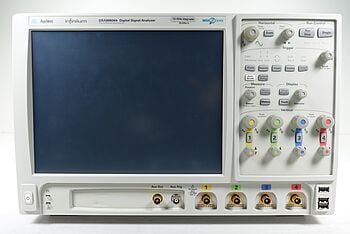
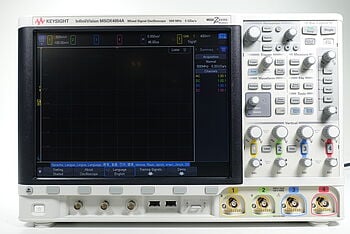
Oscilloscopes, on the other hand, are crucial for visualizing voltage waveforms in time-varying circuits, providing insights into phase relationships and waveform characteristics that are fundamental in AC circuit analysis.
Keysight's premium used equipment is a reliable and cost-effective solution for engineers and educators applying KVL. Offering a range of meticulously refurbished measurement tools, Keysight ensures that even budget-conscious professionals can access high-quality equipment.
These tools not only uphold the standards of precision required for accurate KVL application but also support a sustainable approach by extending the life of valuable measurement technologies.
"All our equipment is Premium Used. I don’t like to call it just “used”, because it’s so much more than used equipment." – Keysight Account Manager
Maximize Your Budget without Compromising Quality with Keysight
Conclusion: Empower Your Circuit Analysis with Keysight's Precision Tools
In this analysis of Kirchhoff’s Voltage Law, we’ve given you the tools you need to solve complex circuits without the frustration of trial and error. You should now have a solid understanding of KVL and practical strategies to master circuit analysis.
We've discussed the core principles of KVL, its application in a wide range of circuits, and the undeniable importance of precise, reliable measurement tools in bringing theory to life.
The right strategy, backed by the right tools, doesn't just simplify challenges—it opens doors to innovation. Let Keysight's precision tools be the key that unlocks these doors, guiding you through the complexities of circuit analysis towards engineering breakthroughs and personal mastery.
Whenever You’re Ready, Here Are 5 Ways We Can Help You
- Browse our premium used network analyzers, oscilloscopes, signal analyzers and waveform generators.
- Call tech support US: 1 800 829-4444
Press #, then 2. Hours: 7am – 5pm MT, Mon– Fri - Talk to our sales support team by clicking the icon (bottom right corner) on every offer page
- Create an account to get price alerts and access to exclusive waitlists
- Talk to your account manager about your specific needs