- Introduction
- TL;DR
- Understanding the Basics of Conductance
- Dissecting the Conductance Formula: G = I/V
- Find Used Impedance Analyzers On Sale
- Conductance and Resistivity
- Exploring Conductance in Series and Parallel Circuits
- Common Misconceptions About Conductance
- Practical Applications of Conductance
- Conductance Calculations and Measurements
- The Future of Conductance in Electrical Engineering
- Why Choose Keysight for Your Electrical Engineering Needs
- Glossary of Terms
- Final Thoughts from Keysight
- Whenever You’re Ready, Here Are 5 Ways We Can Help You
- Find Used Impedance Analyzers On Sale
"As we power towards the future, the concept of conductance has become more crucial than ever in electrical engineering. The nuances of this fundamental concept are guiding us towards smarter, more efficient technology, and are challenging us to continually redefine the boundaries of possibility." – Dr. Jane Willow, Professor of Electrical Engineering, MIT.
A crucial aspect of electrical engineering lies in its core principles, in the fine balance between theory and application, between numbers and practical design. Amid these principles, the conductance formula consistently holds a special place. It's a fundamental concept, a staple in every electrical engineer's toolkit, and a go-to when you need to unlock the mysteries of current and voltage. It is in electrical circuits' health monitoring, power distribution optimization, and innovations aiming to redefine our energy efficiency standards.
At first glance, the idea of conductance can seem complicated. It's full of technical terms and calculations. But what if we break it down? Whether you're an experienced engineer, an engineering student, or a tech enthusiast, this guide is for you. We have created this guide to provide a thorough explanation of conductance and its formula, while maintaining technical precision.
Let's dive into the dynamic world of conductance and decode the formula that underpins so much of our technological world.
TL;DR
- Conductance is a fundamental principle in electrical engineering that measures how easily electric current can flow through a component. It's represented by the symbol 'G' and measured in siemens (S).
- The formula for conductance is G = I/V, where 'I' stands for current and 'V' for voltage. Understanding each component in this formula is crucial for its practical application.
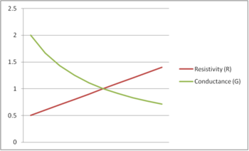
- Resistivity and conductance are inversely related, which is a key concept when designing and analyzing electrical circuits.
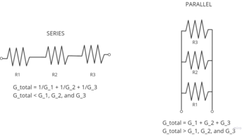
- Conductance behaves differently in series and parallel circuits. In series circuits, total conductance is less than the smallest conductance value, while in parallel circuits, total conductance is greater than the largest conductance value.
- Common misconceptions include confusing conductance with resistance and assuming higher conductance always means better performance. In reality, the optimal conductance value depends on the specific application.
- Practical applications of conductance range from designing electronic circuits to determining the performance of everyday electrical appliances. Tools like ohmmeters, ammeters, voltmeters, LCR meters, and oscilloscopes are commonly used for measuring conductance.
- The study of conductance is also integral to emerging trends in electrical engineering, including nanotechnology and the exploration of novel materials like graphene.
By understanding and applying the principles of conductance, electrical engineers can optimize circuit designs, improve the performance of electronic devices, and prepare for the future of the field.
Understanding the Basics of Conductance
In the world of electrical engineering, we frequently encounter the need to analyze how easily an electric current can flow through a component. Whether it's troubleshooting circuit issues, designing energy-efficient systems, or enhancing the performance of electrical grids, the concept of conductance frequently takes center stage.
Conductance, in simple terms, is the measure of a material's ability to conduct electric current. It's the reciprocal of resistance – while resistance impedes the flow of current, conductance facilitates it. A material with high conductance allows current to pass through it easily, whereas a material with low conductance does the opposite.
Symbolized by 'G', conductance is measured in siemens, represented by the symbol 'S'. Its value can be calculated using the formula G = I/V, where 'I' is the current passing through the object (measured in amperes) and 'V' is the voltage across it (measured in volts).
The significance of conductance in electrical engineering cannot be understated. It forms the basis of Ohm's Law, which is the cornerstone of electrical and electronic circuits. By knowing the conductance of a component, engineers can predict and manipulate the behavior of electrical circuits, optimizing for power efficiency, performance, and safety.

| Key Takeaway |
|---|
| Conductance is a fundamental concept in electrical engineering, symbolized by 'G.' It measures how easily electric current can flow through a component. Its knowledge is critical in predicting and manipulating the behavior of electrical circuits, laying the groundwork for safe, efficient, and high-performing designs. |
Dissecting the Conductance Formula: G = I/V
When we look closely at the formula for conductance, G = I/V, it becomes evident that each component plays a critical role in defining the flow of electric current.
In this formula:
- 'G' is the conductance. It quantifies the ease with which electric current passes through a material. The unit of conductance is siemens (S).
- 'I' is the current, measured in amperes (A). It is the flow of electric charge per unit of time through a material.
- 'V' is the voltage measured in volts (V). It represents the electric potential difference between two points in a circuit and drives the flow of current.
In essence, the conductance formula tells us that the conductance of a component is directly proportional to the current passing through it and inversely proportional to the voltage across it. Therefore, if the voltage remains constant, an increase in current will increase the conductance, and vice versa. Similarly, if the current remains constant, an increase in voltage will decrease the conductance, and vice versa.
| Component | Symbol | Units | Significance |
| Conductance | G | Siemens (S) | It indicates how easily electric current can pass through a material. A higher conductance means a material allows more current to flow. |
| Current | I | Amperes (A) | It is the rate of flow of electric charge. More current implies a greater quantity of charge flowing per unit of time. |
| Voltage | V | Volts (V) | It is the electrical force driving the current. A higher voltage implies a greater force pushing the current through a circuit. |
Each of these components is interrelated, as described by the conductance formula. Understanding their roles and relationships is crucial in electrical engineering to control the behavior of electrical circuits effectively.
Find Used Impedance Analyzers On Sale


Conductance and Resistivity
While conductance refers to a material's ability to allow the flow of electric current, resistivity characterizes a material's inherent opposition to that flow. They represent opposite facets of electrical property, hence they share an inverse relationship. If a material has high conductance, it has low resistivity, and vice versa.
Resistivity, symbolized by 'ρ' (rho), is a property intrinsic to the material itself and does not depend on the dimensions of the component. It is measured in ohm meters (Ω.m). The resistivity of a material helps determine the resistance (R) offered by a specific component, using the formula R = ρL/A, where 'L' is the length of the component and 'A' is its cross-sectional area.
Given that resistance is the reciprocal of conductance, we can rewrite the conductance formula in terms of resistivity as G = A/(ρL). From this formula, it's clear that conductance is directly proportional to the cross-sectional area of the component and inversely proportional to its length and the material's resistivity.
Understanding the relationship between conductance and resistivity is key in designing and analyzing electrical and electronic circuits. It helps engineers make informed decisions about material choice and component dimensions to meet specific design requirements, such as power efficiency, durability, and performance.
| Key Takeaway |
|---|
| Conductance and resistivity are inversely related. When applied appropriately, the resistivity formula can help determine an electronic component's conductance. This relationship is a fundamental principle in electrical engineering and serves as a basis for efficient and effective circuit design. |
Exploring Conductance in Series and Parallel Circuits
Understanding how conductance behaves in different circuit configurations – specifically, series and parallel circuits – is essential for analyzing and designing efficient electrical systems.
In series circuits, the total conductance (G_total) is calculated using the formula 1/G_total = 1/G_1 + 1/G_2 + ..., where G_1, G_2, ... are the conductances of individual components. This formula might seem counter-intuitive, as the total conductance of a series circuit is less than the conductance of the smallest component in the series.
In contrast, in parallel circuits, conductances simply add up. The total conductance of a parallel circuit (G_total) is the sum of the conductances of all the components, i.e., G_total = G_1 + G_2 + ... . This means that the total conductance of a parallel circuit is always greater than the conductance of any individual component.
Key differences between conductance in series and parallel circuits include:
- In a series circuit, the total conductance is less than the conductance of any individual component. In contrast, in a parallel circuit, the total conductance is greater than the conductance of any individual component.
- The total conductance of a series circuit decreases when more components are added, while the total conductance of a parallel circuit increases when more components are added.
- The conductance in a series circuit is calculated by taking the reciprocal of the sum of the reciprocals of individual conductances. For parallel circuits, the total conductance is the sum of the individual conductances.
Understanding these differences is critical for electrical engineers, as it enables them to design circuits that meet specific requirements for power distribution, energy efficiency, and system performance.
Common Misconceptions About Conductance
The nuanced nature of conductance can lead to several misconceptions that can hinder a proper understanding of the concept and its applications. Let's address some of the most common ones:
Misconception 1: Conductance and resistance are the same.
Correction: While both conductance (G) and resistance (R) relate to the flow of electric current, they are not the same. Resistance refers to the opposition to current flow, while conductance measures the ease of current flow. They are inversely related; if resistance is high, conductance is low, and vice versa.
Misconception 2: Higher conductance always means better performance.
Correction: Higher conductance does mean easier current flow, but it doesn't always translate to better performance. Depending on the circuit design and the desired output, sometimes a lower conductance might be preferable. For instance, in applications requiring voltage regulation or power dissipation, higher resistance (and thus lower conductance) is beneficial.
Misconception 3: Conductance is only relevant in electrical engineering.
Correction: While conductance is a fundamental concept in electrical engineering, its relevance extends to other fields as well. In thermal physics, for example, thermal conductance is an important parameter. Similarly, in fluid dynamics, hydraulic conductance plays a significant role.
Here's a quick summary of these misconceptions and their corrections:
- Conductance and resistance are not the same; they are inversely related.
- Higher conductance doesn't always equate to better performance; it depends on the specific application.
- Conductance is not limited to electrical engineering; it has relevance in thermal physics, fluid dynamics, and other fields as well.
| Key Takeaway |
|---|
| There are several misconceptions about conductance, but a correct understanding of conductance and its nuances can significantly enhance your proficiency and versatility in electrical engineering and beyond. |
Practical Applications of Conductance
Conductance plays a pivotal role in the design and functionality of electronic circuits, and is evident in our everyday electrical appliances. Understanding conductance enables engineers to optimize circuit designs for performance, energy efficiency, and safety.
Consider a simple household device like a toaster. The heating elements in a toaster have been designed with a specific conductance to allow the right amount of current to flow, generating the necessary heat to toast bread. Similarly, in a light bulb, the filament's conductance determines the amount of light and heat produced.
In more complex devices such as signal generators and oscilloscopes, conductance is a vital consideration. For instance, in an oscilloscope, the conductance of various internal components directly affects the signal clarity and precision. A signal generator, on the other hand, relies on components with specific conductances to generate signals of different frequencies and amplitudes.
Here are steps to calculate conductance in practical applications:
- Identify the relevant components in the circuit whose conductance needs to be determined.
- Measure the current passing through the component using an ammeter.
- Measure the voltage across the component using a voltmeter.
- Use the conductance formula G = I/V to calculate the conductance.
| Key Takeaway |
|---|
| Conductance is a key parameter in the realm of electrical engineering, playing a crucial role in the design and functionality of electronic circuits. From everyday household appliances to specialized equipment like signal generators and oscilloscopes, the principle of conductance finds practical application in a wide array of devices. |
Conductance Calculations and Measurements
Measuring conductance accurately is critical in electrical engineering, as it directly influences the performance and safety of electrical systems. A variety of tools and techniques are employed to achieve this precision.
| Tool | Description | Accuracy |
| Ohmmeter | Measures resistance directly, from which conductance can be calculated. | High, but dependent on the quality of the ohmmeter and contact resistance. |
| Ammeter and Voltmeter | By measuring current (I) and voltage (V) across a component, conductance (G = I/V) can be calculated. | High, but dependent on the precision of the measurement devices. |
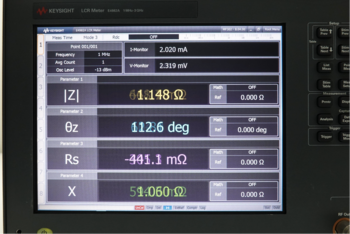
| LCR Meter | Measures inductance (L), capacitance (C), and resistance (R), from which conductance can be calculated. | Very high, especially for components with reactive elements. |
Accurate conductance measurements are of utmost importance as they impact the design, safety, and efficiency of electrical circuits. Here are some tips for ensuring precise measurements:
- Use calibrated tools: Ensure your measurement tools are well-calibrated for precise readings.
- Account for contact resistance: Especially when using an ohmmeter, ensure good contact to avoid inaccuracies due to contact resistance.
- Consider ambient conditions: Temperature and humidity can affect conductance measurements. Try to conduct measurements under controlled conditions.
- For reactive components, use an LCR meter: An LCR meter takes into account inductive and capacitive elements, which can affect the overall conductance.
A solid grasp of conductance calculations and measurements is an invaluable asset in the realm of electrical engineering, contributing to the optimization of circuit designs and the effective operation of electronic systems.
The Future of Conductance in Electrical Engineering
As we forge ahead into the future, the understanding of conductance and its nuances continues to evolve, paving the way for groundbreaking advancements in electrical engineering.
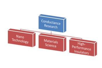
Emerging trends in conductance research include exploration of novel materials like graphene and topological insulators, which exhibit unique conductance properties. Furthermore, the field of nanotechnology is pushing the boundaries of conductance by dealing with electrical components at the molecular level.
These trends hold the potential to revolutionize the electrical engineering landscape, allowing for the development of ultra-fast and energy-efficient electronic devices, improved power systems, and more.
Predictions for the future of conductance in electrical engineering include:
- Conductance at the nanoscale will become a standard topic in electrical engineering due to the rise of nanotechnology.
- The study of conductance in novel materials will lead to the development of new types of electronic devices and components.
- Techniques for measuring conductance will continue to improve, enabling more accurate and precise measurements.
Understanding conductance can benefit future electrical engineers in several ways:
- It provides a solid foundation for the design and analysis of electronic circuits, a core skill for any electrical engineer.
- It equips engineers with the knowledge needed to select appropriate materials and components for specific applications.
- It offers a deeper understanding of emerging fields like nanotechnology and quantum computing, where conductance plays a crucial role.
Conductance remains a fundamental concept in electrical engineering, with exciting new developments on the horizon. As such, a solid understanding of conductance is as relevant as ever, promising to empower the electrical engineers of the future.
Why Choose Keysight for Your Electrical Engineering Needs
Keysight Technologies, a renowned name in the realm of electronic measurement, offers exceptional products and services that cater to a wide range of electrical engineering needs. Whether it's used equipment or calibration services, Keysight stands out as your trusted choice.
Reasons to choose Keysight for your electrical engineering needs include:
- Quality Assurance: Keysight ensures each piece of used equipment meets the original product specifications. This assurance means you can trust the performance and reliability of your purchase.
- Vast Product Range: From oscilloscopes to network analyzers, signal generators to power supplies, Keysight offers a comprehensive range of used equipment catering to diverse needs.
- Unique Calibration Services: Keysight's calibration services are about accuracy, exceptional measurement quality, and reliability. Their calibration services help ensure your tools deliver accurate and precise measurements consistently.
- Expert Support: Keysight provides expert support to help you troubleshoot any issues and get the most out of your equipment.
- Sustainable Choice: By opting for used equipment, you're making a sustainable choice, contributing to the circular economy and helping reduce electronic waste.
In a field where precision, reliability, and quality are paramount, Keysight shines brightly. Opting for Keysight's used products and services not only equips you with superior tools but also provides peace of mind that you're getting exceptional value and backing from a trusted industry leader.
Glossary of Terms
In the study and application of conductance, several key terms, symbols, and units are consistently used. Familiarity with these terms can enhance your understanding and application of conductance principles.
| Term | Definition | Example |
| Conductance (G) | Measure of how easily electric current can flow through a component. | The conductance of a resistor is 1/Resistance. |
| Resistance (R) | The opposition to the flow of electric current. | A resistor of 0.1 ohm has a conductance of 10 siemens. |
| Siemens (S) | The unit of conductance in the International System of Units (SI). | A wire with a conductance of 2 S allows twice the current to pass compared to 1 S for the same applied voltage. |
| Ohm's Law | It states that the current through a conductor between two points is directly proportional to the voltage across the two points (I=V/R). | In a circuit where voltage is 10 volts and resistance is 5 ohms, the current would be 2 amperes. |
| Oscilloscope | A device used for viewing the exact wave shape of an electrical signal. | An oscilloscope can be used to measure the voltage waveform in a circuit. |
| Ammeter | A tool for measuring current. | An ammeter can be used to measure the current flowing through a resistor. |
| Voltmeter | A tool for measuring voltage. | A voltmeter can be used to measure the voltage drop across a resistor. |

Final Thoughts from Keysight
To grasp the fundamentals of electrical engineering, understanding the concept of conductance is key. By revisiting the essential formula, G = I/V, we recognize the significance of conductance in determining how easily electric current can flow through a component.
From clarifying common misconceptions to illuminating practical applications, we've seen how conductance plays an integral role in circuit design and the operation of everyday appliances. Notably, the future of conductance promises to unveil exciting advancements, from nano-electronics to quantum computing.
As an electrical engineer, honing your skills in measuring conductance and learning to navigate the emerging trends in conductance research will undoubtedly open new horizons. In this journey, Keysight's used equipment store stands as a trustworthy ally. Offering quality-assured, pre-owned equipment, unique calibration services, and expert support, Keysight helps you apply your conductance knowledge to your projects effectively and affordably.

Whenever You’re Ready, Here Are 5 Ways We Can Help You
- Browse our Premium Used Oscilloscopes.
- Call tech support US: 1 800 829-4444
Press #, then 2. Hours: 7am – 5pm MT, Mon– Fri - Talk to our sales support team by clicking the icon (bottom right corner) on every offer page
- Create an account to get price alerts and access to exclusive waitlists
- Talk to your account manager about your specific needs